Method for settling of suspensions with use of seepage force and vibrations

Inactive Publication Date: 2002-06-11
TER STEPANIAN KARINE +1
View PDF5 Cites 0 Cited by
  • Summary
  • Abstract
  • Description
  • Claims
  • Application Information

AI Technical Summary

Benefits of technology

It is the object of this invention to provide an effective and inexpensive method for settling of suspensions.
Such behavior of suspensions is a result of action of the suspension force. This force is generated by friction between immovable water and sinking solid particles. This force had been discovered, and its properties were investigated by the inventor. That made it possible to propose the present method of settling without any addition of chemicals, or other special treatment.
An effective method of settling of tailings and the like is of great importance. It will permit the recovery and use of the mineral resources contained in waste, and accumulated in tailings ponds. An incredible quantity of these mineral resources is lost: one third of phosphate mined in Florida, one half of tin mined in Bolivia and one fifth of the world's tungsten. Settling of tailings has a number of advantages. The tailings after settling can be used as building and road materials. Valuable land occupied by tailings ponds can be returned to the national economy. Water and soluble chemical reagents used in technological process will be recycled. The demand for fresh water will be kept to a minimum. Finally the threat of disasters on bursting of tailings dams can be removed.

Problems solved by technology

The industry incurs immense material losses measured annually by billions of dollars.
In spite of these facts the problem remains unsolved for more than a century.
The situation was so hopeless that the problem was considered officially as an unsolvable one.

Method used


Image

  • Method for settling of suspensions with use of seepage force and vibrations
  • Method for settling of suspensions with use of seepage force and vibrations
  • Method for settling of suspensions with use of seepage force and vibrations

Examples


embodiments and processing

11. Embodiments and Processing

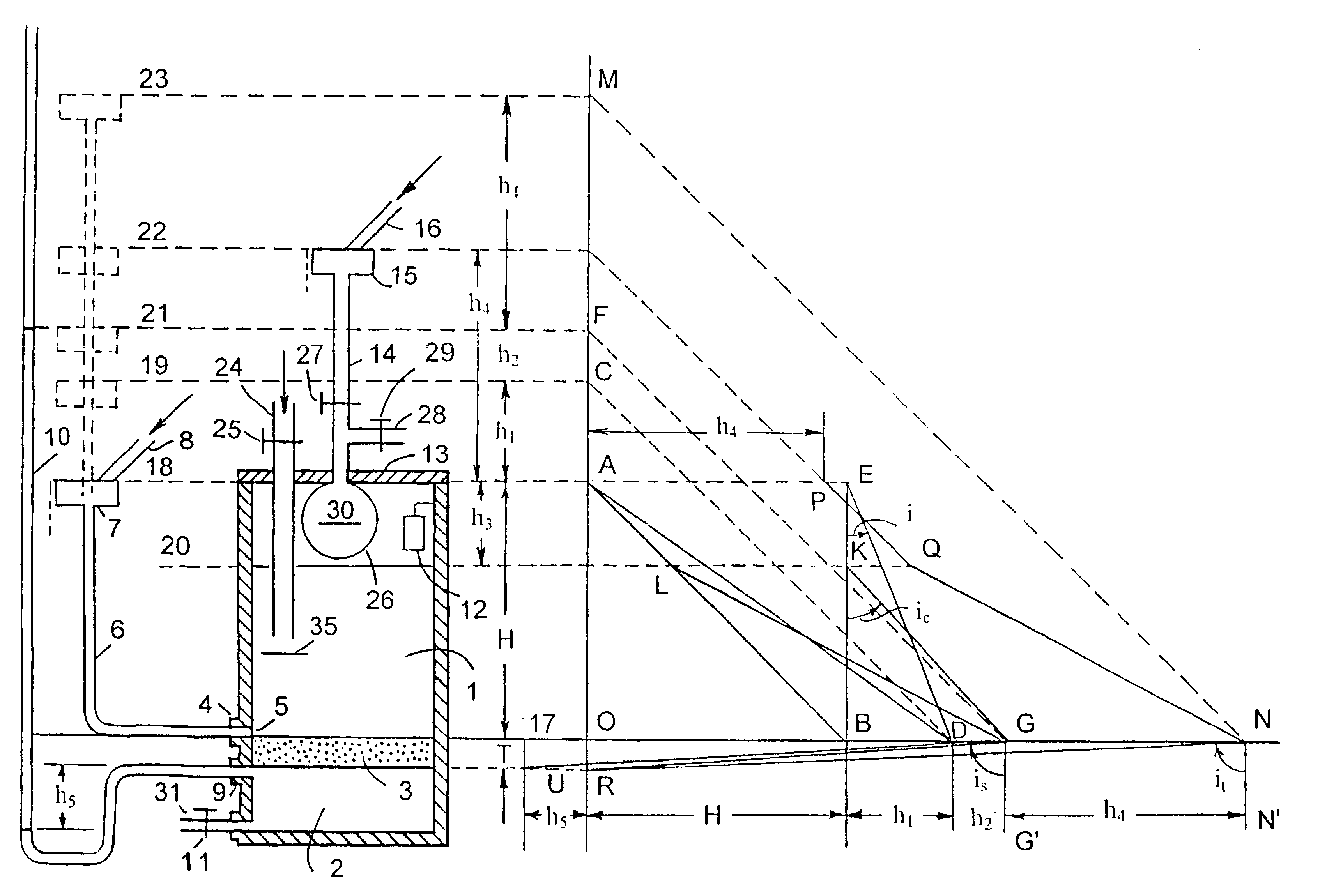
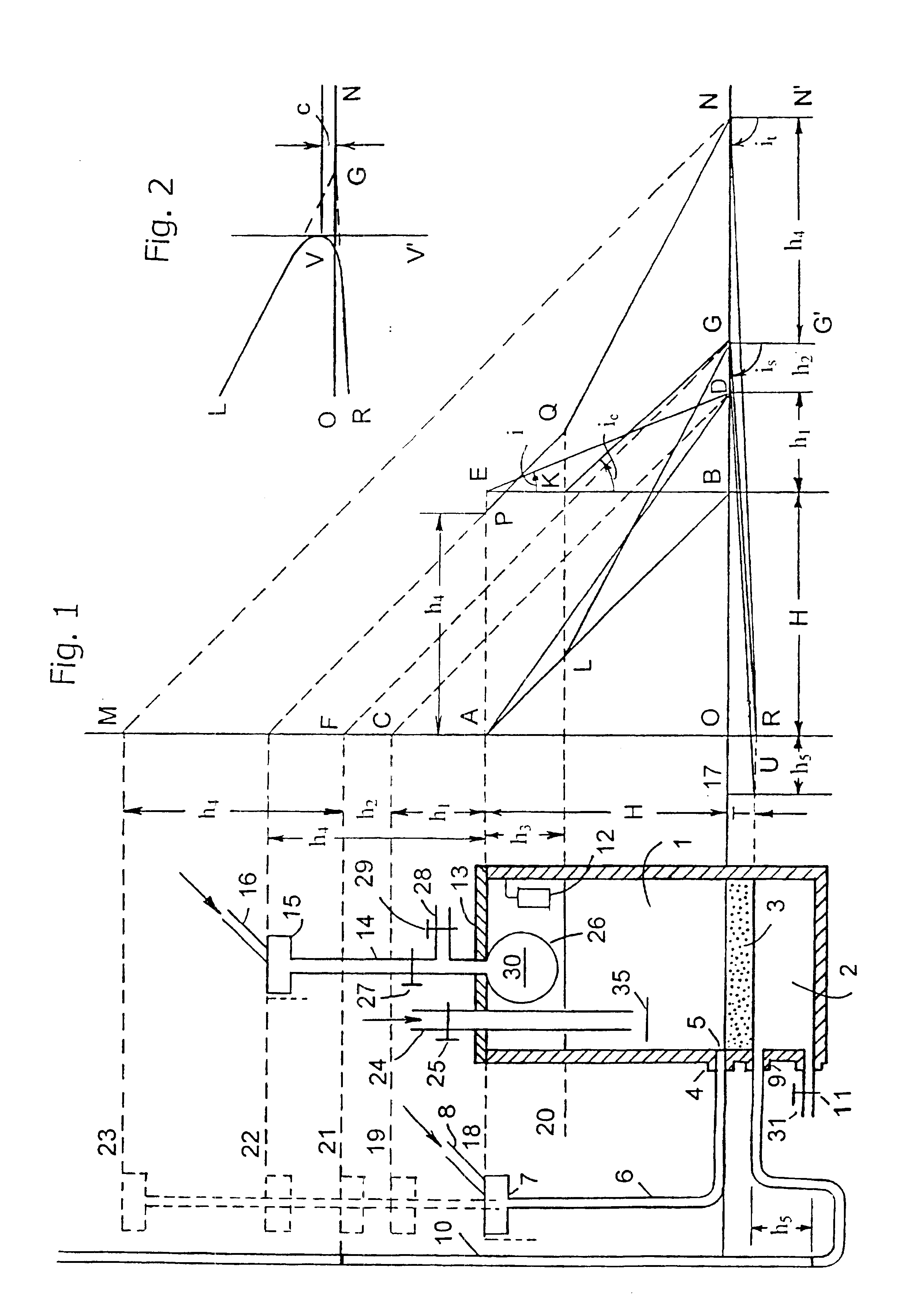
The invention comprises the basic method consisting in application of the seepage force for settling of suspensions or purification of liquids. There are also several supplementary methods as vibrating, diluting, leaving the protecting layer of sediment on the permeable member, increasing the hydrostatic pressure, vacuuming, and isolating the liquid in the closed container from direct contact with water. Combining the basic method with the others, it is possible to find the correct procedure for settling of different types, compositions and states of particular suspensions, and purifying the liquids.

Depending on physical properties of suspensions a number of types of embodiments of the present invention may be implemented, and working regime predetermined based on laboratory and / or pilot experiments. Only principal schemes but not engineering design of different embodiments are shown below. For the sake of clarity and brevity the container 1 will be cal...

first embodiment

The first embodiment is appropriate for suspensions that need an intermediate seepage force for destroying the suspension force.

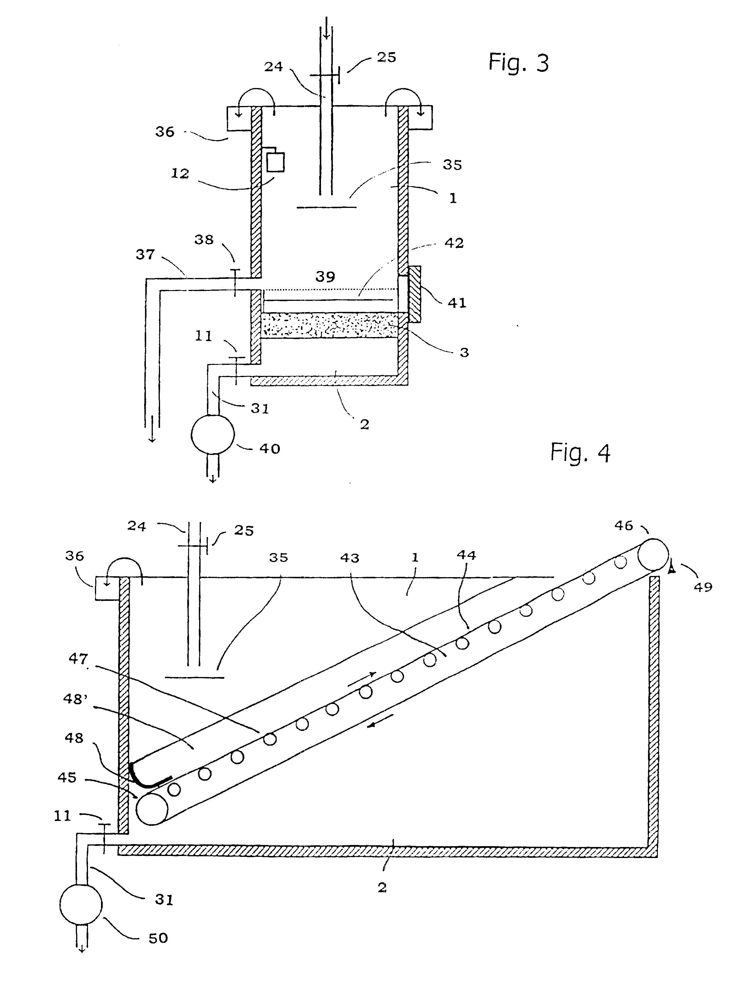
The second possible embodiment of the invention represents an open container where an inclined conveyor 43 wit filtrating belt 44 serves as permeable member 3 (FIG. 4). The idler conveyor pulley 45 is disposed at depth at one end of the container; the driving conveyor pulley 46 is disposed above the container rim at the opposite end. The conveyor belt is rising gradually. The belt is supported by a series of rollers 47. A continuous flexible watertight apron 48 is fastened at face and two longitudinal walls of the container parallel to conveyor belt. The cross-section of the apron designated by 48 is shown at end wall of the container, and the front view designated by 48'--at the longitudinal wall. The apron 48 is placed on the face and sides of the conveyor belt 44 in order to eliminate the passage of suspension by-pass the conveyor belt. The sediment is s...

second embodiment

The second embodiment is appropriate for suspensions needing a low seepage force for destroying the suspension force and has high productivity.

The third possible embodiment represents a closed container (FIG. 5). Three tubes are installed on lid 13: feeding tube 24 with valve 25 and flap 35, pressure tube 14 with outlet 28 and valves 27 and 29, and a short standpipe 51 with valve 52. The suspension is supplied through feeding tube 24. Flap 35 serves for eliminating the vertical jet in the suspension. High hydrostatic pressure is transmitted through tube 14 connected with a conventional pressure tank (not shown in FIG. 5). Outlet 28 with valve 29 serves for removal of supernatant for recycling. Short standpipe 51 with valve 52 serves for communication with atmosphere. A discharging outlet 37 with valve 38 is disposed at the middle part of closed container at a certain height above permeable member 3 (level 39, shown by a dotted line) as that in the first embodiment. Vibrator 12 is in...


PUM

PropertyMeasurementUnit
Weightaaaaaaaaaa
Timeaaaaaaaaaa
Thicknessaaaaaaaaaa

Abstract

The inability to settle mining tailings, pumps, slurries, and other wastes in form of hard sediments and forced storage of jelly-like sludge in tailings ponds have a great economic and environmental impact. This feature is caused by suspension force arising due to high neutral pressure. The drag caused by friction between sinking solid particles and immovable water generates the upward directed suspension force that decreases the unit weight of solid particles, and they settle extremely slowly. On sufficient concentration of solid particles they become weightless and further settling is ceased. The solid particles remain suspended for a long time. The suspension force can be destroyed by greater oppositely directed seepage force. For this purpose the suspension is supplied into a container with permeable member, low pressure acting on its downstream surface is ensured, and passage of liquid through the permeable member is initiated. A downward directed seepage force is formed in the permeable member. A rather rapid settling of solid particles occurs, and dense sediment is obtained. A number of auxiliary methods can be used, such as vibration for destroying loose structure formed by rigid angular grains, diluting of thick suspensions for initiating seepage, vacuuming for increasing the hydraulic gradient in open containers, applying supplementary hydrostatic pressure above the permeable member for increasing the hydraulic gradient in closed containers, and using conveyors for continuous processing. The method can be used for purification of liquids by settling the impurities.

Description

BACKGROUND OF THE INVENTIONThe present invention relates to settling of thick suspensions.Suspensions are formed in many types of technology, usually as industrial wastes. Among suspensions are tailings, pulps, refuse, and contaminated earth. Tailings are the most important .[.Types.]. .Iadd.types .Iaddend.of wastes from both economical and ecological standpoints.For better extraction of ores the rocks are ground to silt-and clay-size fraction. After ore benefaction the tailings are transported to tailings ponds for storage. The solid concentration in the initial slurry is different. The slurry discharged from the mill contains usually from 15 to 55% of solids.The suspension in tailings ponds settles with decelerating rate. The mass is separated into supernatant and rather dense slurry containing higher concentration of solids.Following the initial period of settling, the process becomes extremely slow. An idea of the duration of the process may be gained from the distribution of un...

Claims


Application Information

Patent Timeline
IPC IPC(8): B01D21/00B01D17/02B01D17/00B01D17/04
CPCB01D17/00B01D17/0208B01D17/0211B01D17/0214B01D17/044B01D17/047B01D17/085B01D21/00B01D21/0012B01D21/0024B01D21/18B01D21/24B01D21/2405B01D21/2416B01D21/2444B01D21/2455B01D21/2488B01D21/283B01D21/30B01D21/34B01D2221/04
Inventor TER-STEPANIAN, GEORGE
Owner TER STEPANIAN KARINE
Why Eureka
Try Eureka