Synthetic rope socket with solid thimble

a technology of synthetic rope and socket, which is applied in the direction of mechanical equipment, ropes and cables for vehicles/pulleys, belts/chains/gearings, etc., can solve the problems of increased labor hours, long installation time, time-consuming and expensive, etc., and achieves the effect of fast and efficient field assembly and 100% efficiency of the tensile strength of the subj

Inactive Publication Date: 2020-08-27
WASHINGTON CHAIN & SUPPLY
View PDF0 Cites 5 Cited by
  • Summary
  • Abstract
  • Description
  • Claims
  • Application Information

AI Technical Summary

Benefits of technology

[0004]The inventive synthetic rope socket includes a braided rope tapered solid compression thimble and enclosing tapered socket with screw-on cap used for the end termination of braided synthetic ropes offering 100% efficiency of the tensile strength of the subject synthetic rope and ease of connections. With the design of this apparatus it will allow for quick and efficient field assembly. The design of the apparatus will allow for the connection of synthetic ropes to other devices such as chains, wire ropes, and even other synthetic ropes without the need for intermediate hardware designed for the protection of the synthetic rope. The apparatus also has the capabilities of being customized to fit any connection point with the removable screw-on cap.

Problems solved by technology

The synthetic rope fittings have been large, heavy and cumbersome resulting in long installation times, increased labor hours, and safety concerns for employees.
The current method of terminating a synthetic rope with a metal connector requires sending the rope to specialized connector manufacturers for in-house mating of the rope to the specialized socket and is time consuming and expensive.

Method used


Image

  • Synthetic rope socket with solid thimble
  • Synthetic rope socket with solid thimble
  • Synthetic rope socket with solid thimble

Examples


Embodiment Construction

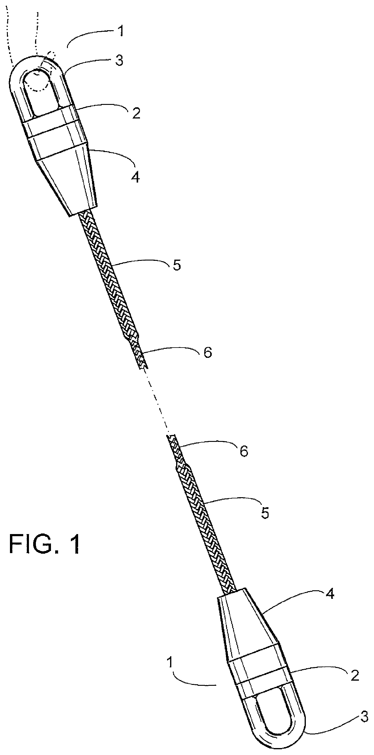
[0021]FIG. 1 is illustrative of the use of the inventive synthetic rope socket 1 to terminate both ends of a braided synthetic rope 6. There is shown a synthetic rope splice 5 extending from the rope exit end and rope entry end 14 of an enclosing thimble socket 4 that is attached to a screw-on cap 2 with a fitting end 3 shown as an eye.

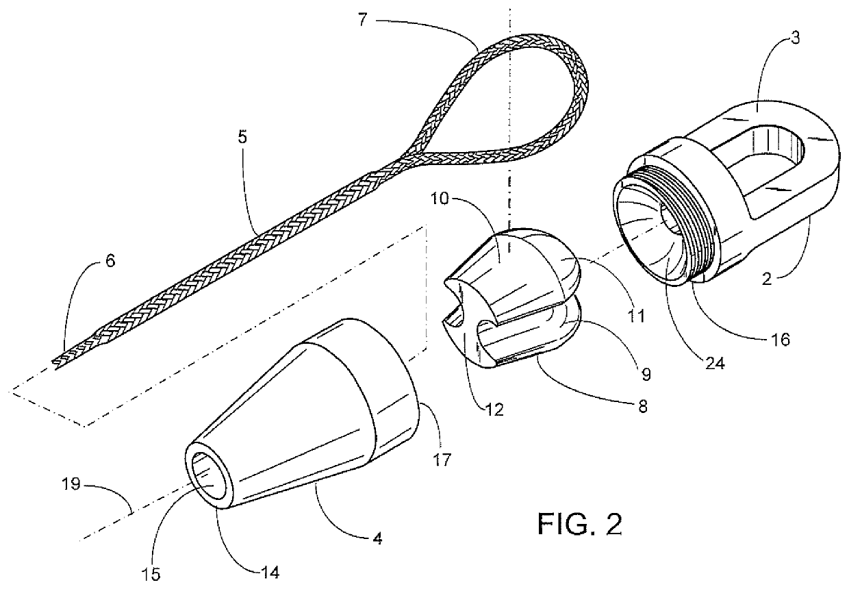
[0022]In FIG. 2, the inventive synthetic rope socket is exploded along a longitudinal axis 19 to show a tapered solid compression thimble 8 having tapered sides 10, a spherical top end 11, a bottom or rope entry end and rope exit end 12 and a longitudinal exterior contour groove 9. Above the tapered solid compression thimble 8 is shown a screw-on cap 2 with a fitting end 3 and external threads 16. Below the tapered solid compression thimble 8 is shown an enclosing thimble socket 4 with a rope entry end and rope exit end 14, a rope entry opening and rope exit opening 15 and a solid compression thimble entry end 17. For clarity, a braided synthetic rope...


PUM


Abstract

A device and method for the end termination of a braided synthetic rope offering full efficiency of the spliced and unspliced, tensile strength of the subject synthetic rope, with a tapered solid compression thimble of unique surface topography allowing forces on the tapered solid compression thimble only in compression, seated inside an enclosing thimble socket with an internal tapered thimble seat free of sharp edges, with a screw-on cap at the top of the enclosing thimble socket with a fitting for attachment for connecting links and configurable for different rigging attachment styles, a contoured groove in the tapered solid compression thimble for receiving a braided synthetic rope wrapped around the solid compression thimble and spliced into itself. Rounded edges at the bottom of the enclosing thimble socket help protect the braided synthetic rope from abrasion and cutting while in service. Also provided is a screw-on cap with an adjustable externally threaded extension rod to receive an internally threaded clevis jaw and pin end fitting positioned as desired on the extension rod with a lock nut. The device is intended to create a job-site qualified, safe and efficient manner to connect objects in the rigging and mooring industry such as other synthetic mooring lines, tow lines, anchor chains, and wire ropes.

Description

[0001]This application is a Continuation-in-part of application Ser. No. 16 / 174,990 (the ‘990 application’) filed Oct. 30, 2018, co-owned with the present invention. The '990 application is incorporated here by reference for all purposes, and with respect to all of which the present invention claims priority under United States Patent Law.BACKGROUND OF THE INVENTION[0002]The invention relates to a device and method for the end termination of a braided synthetic rope that is currently being used in the mooring of any or all offshore drilling, and production facilities, towing and other crane & rigging applications. Moreover the invention relates to a preferably alloy metal termination, or other suitably engineered material, of braided synthetic rope which will enhance the protection of mooring lines and other synthetic rope applications at the end fitting, will reduce installation times in turn reducing costs, and will utilize standard wire rope, and / or chain connectors. The device a...

Claims


Application Information

Patent Timeline
Patent Type & Authority Applications(United States)
IPC IPC(8): F16G11/14F16G11/04F16G11/02
CPCF16G11/046F16G11/025F16G11/146
Inventor BENAVIDEZ, GABRIELROW, STEVEEGGERS, LANCEFIEDLER, JORDAN A.
Owner WASHINGTON CHAIN & SUPPLY
Why Eureka
Try Eureka