
Power grid decision-making support device and method, and system applying same

Inactive Publication Date: 2020-08-27
HITACHI LTD
View PDF0 Cites 2 Cited by
  • Summary
  • Abstract
  • Description
  • Claims
  • Application Information

AI Technical Summary

Benefits of technology

The present invention allows for faster presentation of control candidates and provides an operator with decision-making support using control candidate models learned from analysis of accidental events, measurement data, and control data. The technical effect is improved efficiency and effectiveness in controlling and decision-making.

Problems solved by technology

In a power grid, it is difficult to secure the stabilization of the power grid due to the complication of the power grid by renewable energy and the like.

Method used


Image

  • Power grid decision-making support device and method, and system applying same
  • Power grid decision-making support device and method, and system applying same
  • Power grid decision-making support device and method, and system applying same

Examples


example 1

[0047]Example 1 is an example in which a decision-making support system is applied to a power grid stabilization operation.

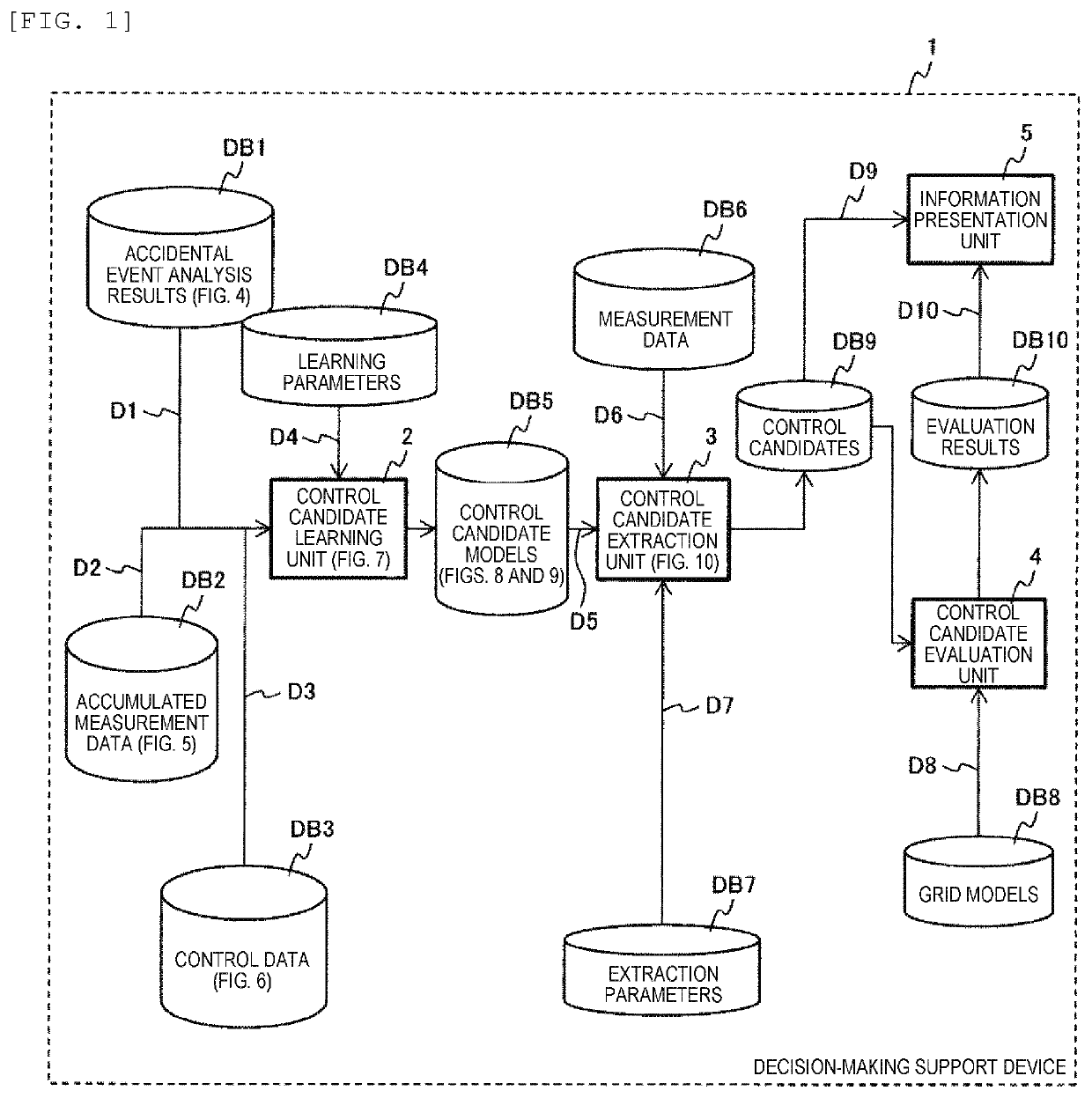
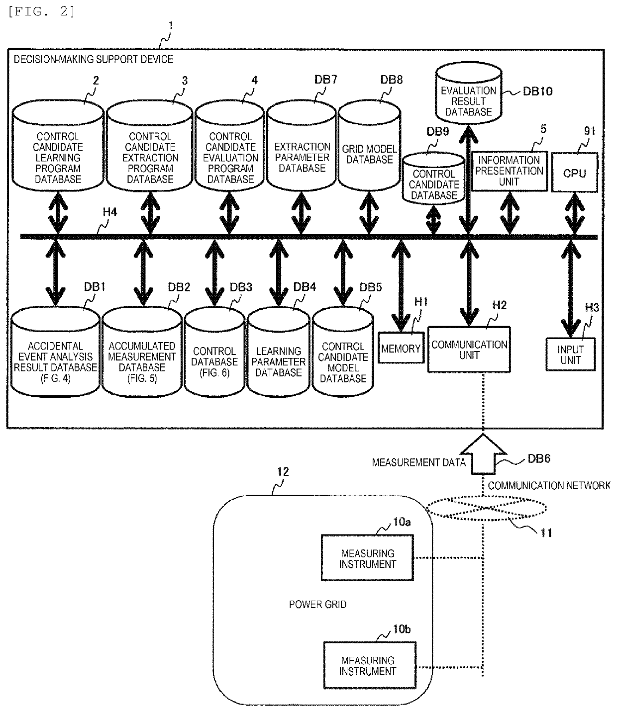
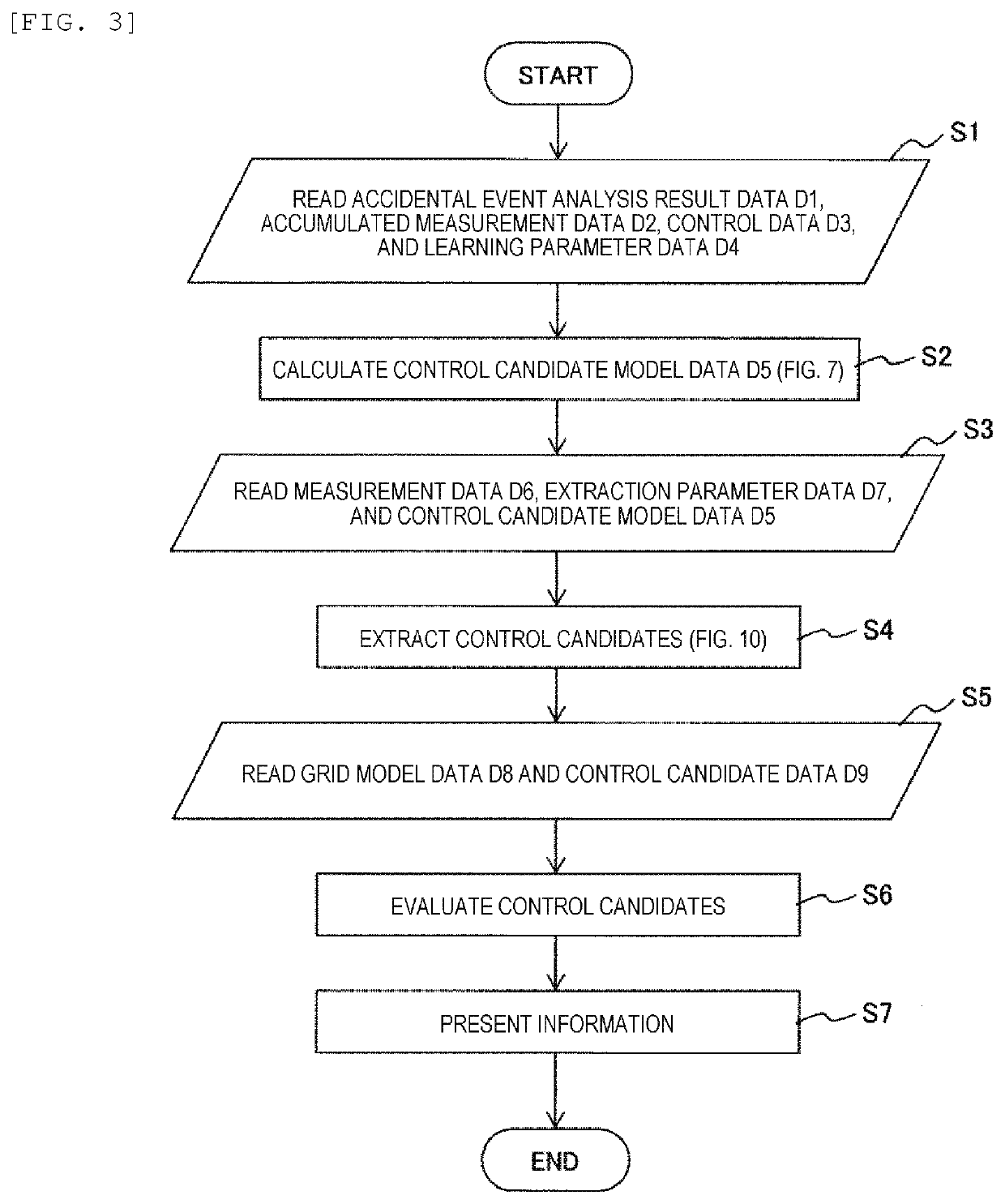
[0048]FIG. 1 is a diagram illustrating an overall configuration example of a decision-making support device 1 according to Example 1. The decision-making support device 1 is configured of a computer system, but in FIG. 1, databases DB possessed by the decision-making support device 1 and the internal processing functions are illustrated in the form of blocks.

[0049]The databases DB possessed internally are an accidental event analysis result database DB1, an accumulated measurement data database DB2, a control data database DB3, a learning parameter database DB4, a control candidate model database DB5, a measurement data database DB6, an extraction parameter database DB7, a grid model database DB8, a control candidate database DB9, and an evaluation result database DB10.

[0050]Among the processing functions, a control candidate learning unit 2 forms the control ca...

example 2

[0106]Example 2 is a configuration example when the decision-making support device 1 of Example 1 is applied to a wide area monitoring protective control system.

[0107]FIG. 17 is a diagram illustrating a configuration example of a wide area monitoring protective control system 20. The wide area monitoring protective control system 20 includes an accidental event calculation device 21 that inputs each data D6, D8, and D11 from the grid model database DB8, the measurement database DB6, and an assumed event database DB11 and outputs an accidental event calculation result; the decision-making support device 1 that outputs the control candidate data D9 by inputting the results; a control command generation unit 22 that outputs a control command by inputting the control candidate data D5; and a control target device 23 that is controlled by the control command. Other parts are the same as those of the decision-making support device 1 in FIG. 1 and thus the description thereof is omitted.

[0...

example 3

[0110]Example 3 is a configuration example when the decision-making support device 1 of Example 1 is applied to a grid operator training system.

[0111]FIG. 19 is a diagram illustrating a configuration example of a grid operator training system 30. The grid operator training system 30 includes the decision-making support device 1 that inputs a virtual data D12 recorded in a virtual data database DB12 and outputs the control candidate data D9 and the evaluation result data D10; the accidental event calculation device 21 that performs accidental event calculation using the grid model data D8 as input; and an operator evaluation unit 32 that performs evaluation of an operator using the simulation result as input. In this system, a grid operator P is interposed and the grid operator P grasps the control candidate data D9 and the evaluation result data D10 sent from the decision-making support device 1 and sends a control command to the accidental event calculation device 21.

[0112]A proces...


PUM


Abstract

In order to provide a power grid decision-making support device and method which are capable of providing operator decision-making support, and quickly presenting control candidates, and a system which applies the same, one representative embodiment of the present invention provides a power grid decision-making support device characterized by comprising: a control candidate learning unit for deriving, by learning, a plurality of control candidate models for stabilizing a power grid; a control candidate extraction unit for extracting, from the plurality of control candidate models derived by the control candidate learning unit, control candidates using power grid measurement data and extraction parameters; a control candidate evaluation unit for evaluating the control candidates using a power grid model and the control candidates; and an information presentation unit for presenting information about the evaluation results and the control candidates.

Description

TECHNICAL FIELD[0001]The present invention relates to a power grid decision-making support device and a method, and a system applying the same.BACKGROUND ART[0002]In a power grid, it is difficult to secure the stabilization of the power grid due to the complication of the power grid by renewable energy and the like.[0003]As a background art of the technical field relating to the present invention, PTL 1 is known. PTL 1 discloses, as an object of the invention, “a support function is easily realized at a low cost by providing a fault-time operation support device separately from a power grid monitor control system, without incorporating a support function inside this system”.[0004]In addition, as a solution thereto, “The fault-time operation support device registers various fault patterns in a support database 10 in advance from the past faults and the like, and registers guidances for dealing with faults, which correspond to the registered fault patterns in a file database 12 in adv...

Claims


Application Information

Patent Timeline
IPC IPC(8): G06Q50/06G06N5/04G06N20/00H02J3/24
CPCH02J3/24G06Q50/06G06N20/00G06N5/04Y04S10/50H02J2203/20H02J13/00001H02J13/00002Y02E60/00Y04S10/30Y04S10/40Y04S40/20H02J3/242Y04S10/22Y02E40/70
Inventor KIRIHARA, KENTAKURODA, EISUKESAITO, NAOHORII, HIROOYATSU, MASAHIRO
Owner HITACHI LTD
Learn More