Axial Flow Turbine

a flow turbine and axial flow technology, applied in the direction of blade accessories, machines/engines, leakage prevention, etc., can solve the problems of loss and loss, and achieve the effect of reducing interference loss and secondary flow loss, and reducing mixing loss

Inactive Publication Date: 2020-09-03
MITSUBISHI HEAVY IND LTD
View PDF0 Cites 0 Cited by
  • Summary
  • Abstract
  • Description
  • Claims
  • Application Information

AI Technical Summary

Benefits of technology

[0010]According to the present invention, it is possible to reduce interference loss and secondary flow loss, and to reduce mixing loss.

Problems solved by technology

Since the part of the working fluid is neither accelerated nor caused to turn by the stator blades, loss occurs.
Since the part of the working fluid does not apply rotational force to the moving blades, loss occurs.

Method used


Image

  • Axial Flow Turbine
  • Axial Flow Turbine
  • Axial Flow Turbine

Examples


Embodiment Construction

[0017]Hereinafter, embodiments of the present invention in cases when the present invention is applied to a steam turbine are explained with reference to the drawings.

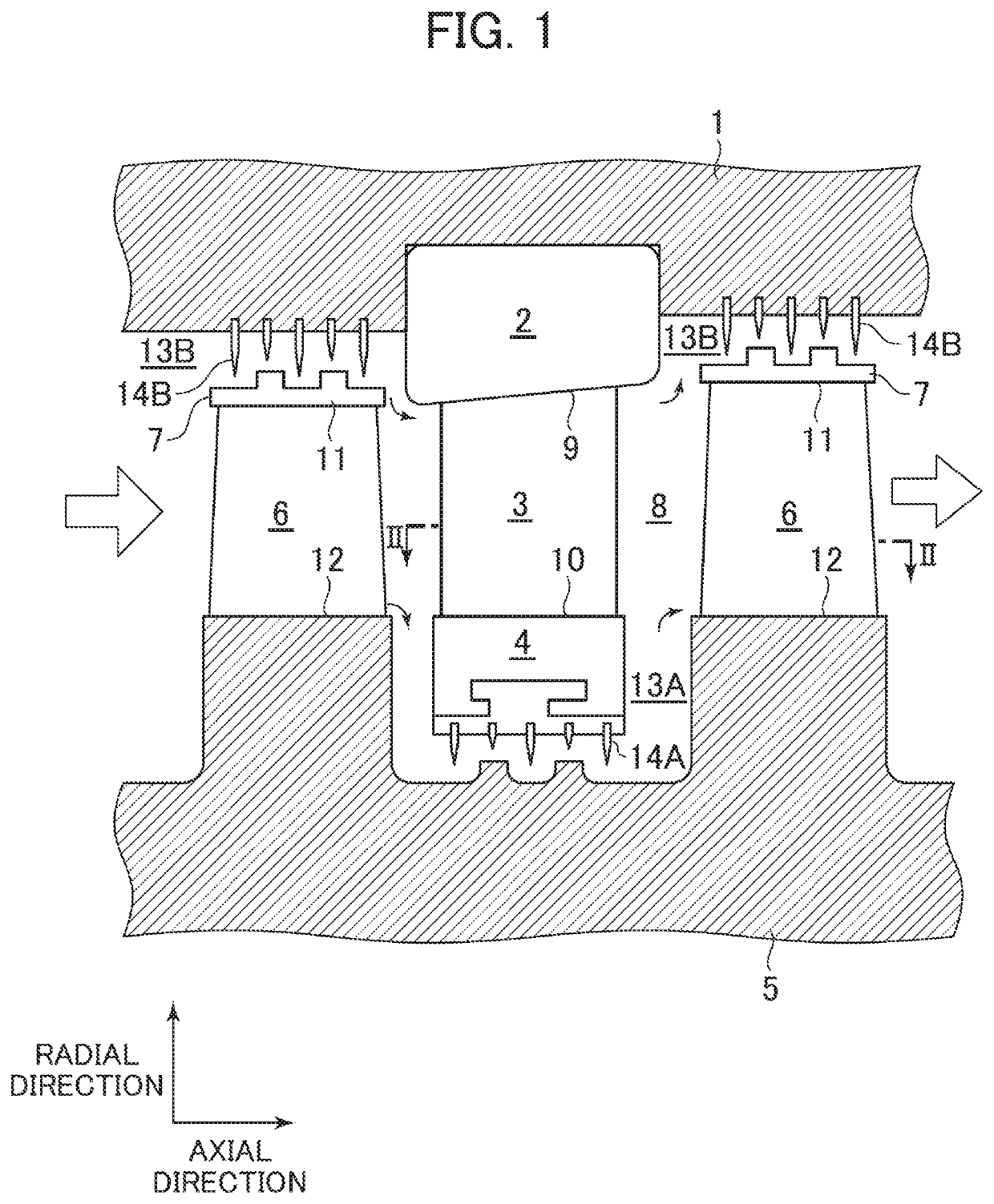
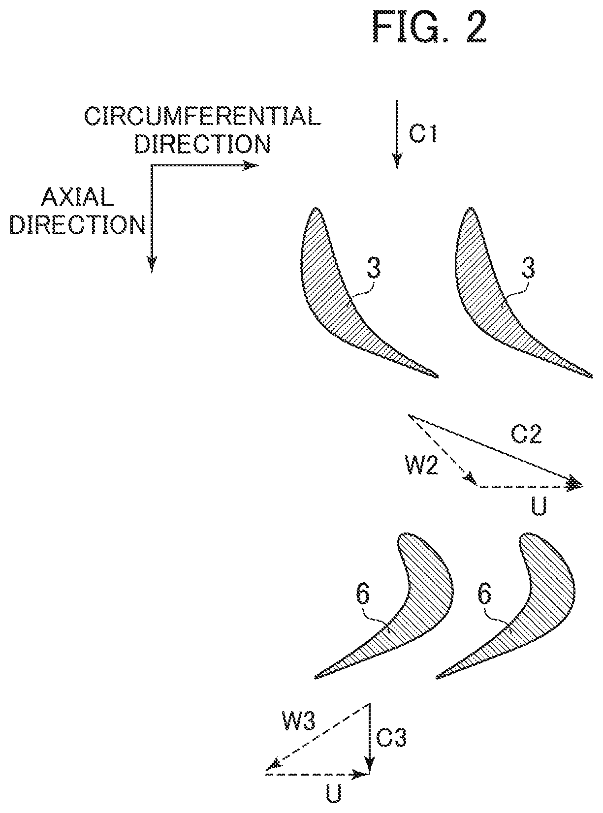
[0018]FIG. 1 is an axial cross-sectional view schematically representing a partial structure of a steam turbine in a first embodiment of the present invention. FIG. 2 is a circumferential cross-sectional view which is taken along the cross-section II-II in FIG. 1, and illustrates a flow in a main flow path.

[0019]The steam turbine in the present embodiment includes: an annular diaphragm outer ring 2 provided on the inner-circumference side of a casing 1; a plurality of stator blades 3 provided on the inner-circumference side of the diaphragm outer ring 2; and an annular diaphragm inner ring 4 provided on the inner-circumference side of the stator blades 3. The plurality of stator blades 3 are arrayed between the diaphragm outer ring 2 and the diaphragm inner ring 4 at predetermined intervals in the circumferential direc...


PUM


Abstract

To provide an axial flow turbine that can reduce interference loss and secondary flow loss, and can reduce mixing loss. An axial flow turbine includes: stator blades provided on the inner-circumference side of a diaphragm outer ring; a diaphragm inner ring provided on the inner-circumference side of the stator blades; moving blades provided on the outer-circumference side of a rotor; a shroud provided on the outer-circumference side of the moving blades; a main flow path constituted by a flow path formed between an inner circumferential surface of the diaphragm outer ring and an outer circumferential surface of the diaphragm inner ring, and a flow path formed between an inner circumferential surface of the shroud and an outer circumferential surface of the rotor; and a cavity formed between the diaphragm inner ring and the rotor. The outer circumferential surface of the rotor has protruding portions and depressed portions. Each depressed portion extends along a relative flow direction of a working fluid passed through the stator blades in the main flow path.

Description

BACKGROUND OF THE INVENTION1. Field of the Invention[0001]The present invention relates to an axial flow turbine used for a steam turbine, gas turbine or the like at power plants.2. Description of the Related Art[0002]For example, an axial flow turbine includes: an annular diaphragm outer ring provided on an inner-circumference side of a casing; a plurality of stator blades that are provided on an inner-circumference side of the diaphragm outer ring, and arrayed in a circumferential direction; an annular diaphragm inner ring provided on an inner-circumference side of the plurality of stator blades; a rotor; a plurality of moving blades that are provided on an outer-circumference side of the rotor and arrayed in the circumferential direction; and an annular shroud provided on an outer-circumference side of the plurality of moving blades.[0003]A main flow path of the axial flow turbine is constituted by a flow path formed between an inner circumferential surface of the diaphragm outer...

Claims


Application Information

Patent Timeline
Patent Type & Authority Applications(United States)
IPC IPC(8): F01D9/04F01D5/02
CPCF05D2240/24F01D9/041F05D2220/30F01D5/021F05D2240/12F01D11/08F01D11/02F01D5/143F05D2240/121F01D5/141F05D2220/32
Inventor SENOO, SHIGEKIMOMMA, KAZUHIRO
Owner MITSUBISHI HEAVY IND LTD
Why Eureka
Try Eureka