Image forming system, image forming apparatus, output method, and storage medium

a technology of image forming and image forming, which is applied in the direction of digital output to print units, instruments, computing, etc., can solve the problems of information leakage, long time for displaying document lists, etc., and achieve the effect of enhancing the convenience of holding printing functions

Inactive Publication Date: 2020-09-03
CANON KK
View PDF2 Cites 1 Cited by
  • Summary
  • Abstract
  • Description
  • Claims
  • Application Information

AI Technical Summary

Benefits of technology

[0006]The present disclosure was made in view of the above-described conventional examples, and it is one object of the present disclosure to provide a mechanism that makes it possible to display an

Problems solved by technology

In this case, there is a possibility that an information leak will occur as a result of the printed matter being left behind or a third party seeing the uncollected printed matter.
However, in conventional technologies, if the above-described hold printing and remote hold printing are dyn

Method used


Image

  • Image forming system, image forming apparatus, output method, and storage medium
  • Image forming system, image forming apparatus, output method, and storage medium
  • Image forming system, image forming apparatus, output method, and storage medium

Examples


embodiment 1

Network Configuration of Remote Hold Printing System

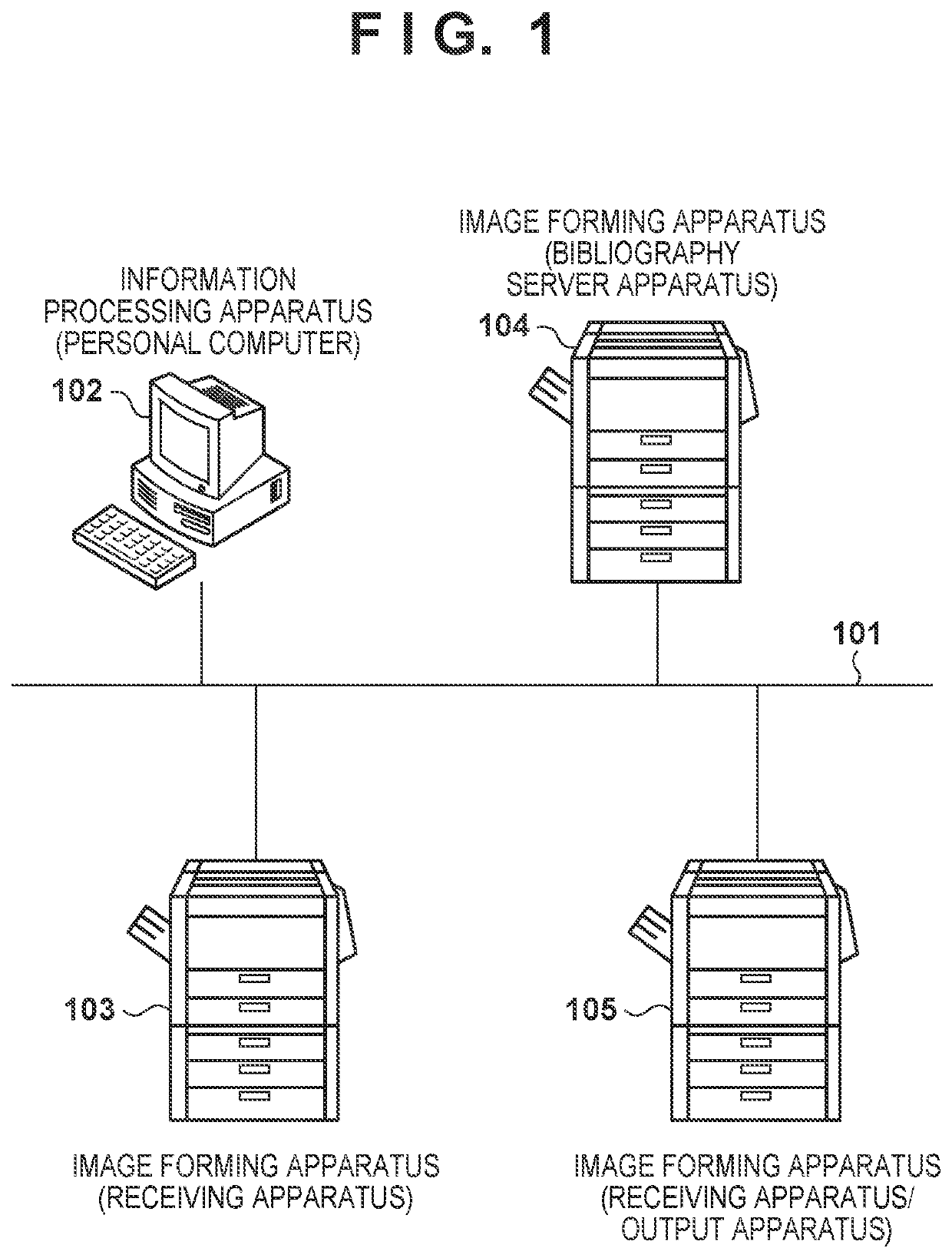
[0025]FIG. 1 is a diagram showing a network configuration to which a multifunction peripheral that is an image forming apparatus according to Embodiment 1 of the present disclosure can be applied. In FIG. 1, a network 101 supports TCP / IP protocols, for example. A personal computer 102, which is an information processing apparatus, and multifunction peripherals 103 to 105 are connected to the network 101.

[0026]For example, the multifunction peripheral 103 is a document receiving apparatus that, upon receiving a print job from the personal computer 102, performs printing or stores (in other words, saves or retains) print data that is included in the print job to perform printing later. The multifunction peripheral 103 extracts bibliographic information from the received print job and transmits the extracted bibliographic information to the multifunction peripheral 104. The multifunction peripheral 104 is a bibliography server apparat...

embodiment 2

[0127]In Embodiment 1, an example is described in which hold printing and remote hold printing are dynamically switched, and bibliographic information stored in the self apparatus is used in the case of hold printing, and bibliographic information acquired from the bibliography server apparatus is used in the case of remote hold printing.

[0128]According to Embodiment 1, in the case of remote hold printing, a document list is displayed by acquiring bibliographic information from the bibliography server apparatus and storing the bibliographic information in the self apparatus, when displaying the list, and therefore display of the list may be delayed. Furthermore, there are cases in which bibliographic information that is acquired from the bibliography server apparatus and stored in the self apparatus overlaps with bibliographic information that is already stored in the self apparatus, and HDD resources are unnecessarily used.

[0129]Therefore, in Embodiment 2, an example will be descri...


PUM


Abstract

An image forming system comprises a document receiving apparatus, an output apparatus, and a bibliography server. The document receiving apparatus comprises a first processor capable of executing first instructions causing the document receiving apparatus to receive and store print jobs. The bibliography server comprises a second processor capable of executing second instructions causing the bibliography server to receive bibliographic information including a storage location of each print job and store the bibliographic information. The output apparatus comprises a third processor capable of executing third instructions causing the output apparatus to acquire the bibliographic information, display the bibliographic information; and acquire a print job selected from the storage location and execute the print job.

Description

BACKGROUND OF THE INVENTIONField of the Invention[0001]The present disclosure relates to an image forming system, an image forming apparatus, an output method, and a storage medium.Description of the Related Art[0002]Conventional multifunction peripherals immediately perform printing upon receiving a print job from a terminal apparatus such as a personal computer (PC). In this case, there is a possibility that an information leak will occur as a result of the printed matter being left behind or a third party seeing the uncollected printed matter. Therefore, in recent years, in order to maintain confidentiality, hold printing has been proposed in which a print job is retained in a nonvolatile storage area, without being printed, upon having been received, and printing is performed thereafter when a print instruction is given from a user through an operation unit of a multifunction peripheral (Japanese Patent Laid-Open No. 2007-251279).[0003]Also, in recent years, remote hold printing...

Claims


Application Information

Patent Timeline
IPC IPC(8): G06F3/12
CPCG06F3/1261G06F3/1288G06F3/1207G06F3/1204G06F3/1237G06F3/1285G06F3/1291G06F3/1267Y02D10/00
Inventor TOKUMOTO, HIROKAZU
Owner CANON KK
Why Eureka
Try Eureka