Unlock instant, AI-driven research and patent intelligence for your innovation.

Vehicle control system and vehicle control method

a vehicle control and control system technology, applied in vehicle position/course/altitude control, process and machine control, instruments, etc., can solve the problem of not being able to accurately identify a user who is remotely operating the vehicle from outside the vehicle in some cases, and achieve the effect of accurately identifying a user

Active Publication Date: 2020-09-10
HONDA MOTOR CO LTD
View PDF0 Cites 1 Cited by
  • Summary
  • Abstract
  • Description
  • Claims
  • Application Information

AI Technical Summary

Benefits of technology

The patent text describes a system and method for controlling vehicles from outside them accurately. This can help identify the person who is remotely driving the car.

Problems solved by technology

However, in the related art, when there are many persons around a vehicle that is being remotely operated on the basis of specific gestures and all the persons are performing the same gesture, it is not possible to accurately identify a user who is remotely operating the vehicle from outside the vehicle in some cases.

Method used


Image

  • Vehicle control system and vehicle control method
  • Vehicle control system and vehicle control method
  • Vehicle control system and vehicle control method

Examples


first embodiment

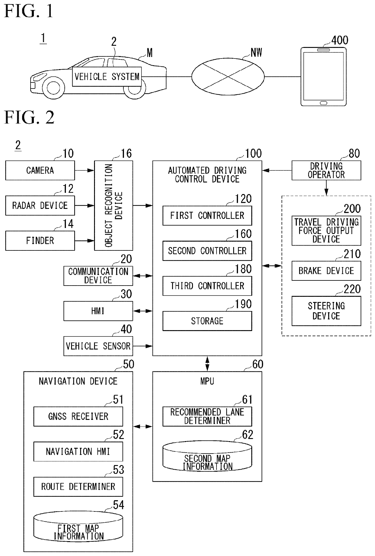
[0033]FIG. 1 is a diagram showing an example of a user identification system 1 according to a first embodiment. The user identification system 1 according to the first embodiment includes a vehicle system 2 mounted in a vehicle M, and a terminal device 400. The vehicle system 2 and the terminal device 400 are connected via a network NW. The network NW includes a local area network (LAN), a wide area network (WAN), and the like. The network NW may include, for example, a network using wireless communication such as Wi-Fi or Bluetooth (registered trademark; the same applies hereinafter), or may include an application server, a web server, or the like.

[0034]The host vehicle M in which the vehicle system 2 is mounted is, for example, a vehicle such as a two-wheeled vehicle, a three-wheeled vehicle, or a four-wheeled vehicle. A driving source thereof includes an internal combustion engine such as a diesel engine or a gasoline engine, an electric motor, or a combination thereof. The elect...

second embodiment

[0135]Hereinafter, a second embodiment will be described. In the first embodiment, a case in which the terminal device 400 is caused to display specific content for causing the host vehicle M to identify the user has been described. On the other hand, the second embodiment is different from the first embodiment described above in that auxiliary content (hereinafter referred to as sub-content) for designating an automated driving aspect of the host vehicle M, that is, an event is included in the specific content to be displayed on the terminal device 400. Hereinafter, differences between the second embodiment and the first embodiment will be mainly described, and a description of respects common to the second embodiment and the first embodiment will be omitted. In the description of the second embodiment, portions that are same as in the first embodiment are denoted with the same reference signs.

[0136]FIG. 12 is a diagram showing an example of a content data 192 according to the seco...


PUM


Abstract

A vehicle control system includes a recognizer configured to recognize first content displayed on a terminal device, and an identifier configured to identify a person carrying the terminal device with the first content displayed thereon outside the vehicle as a user scheduled to use the vehicle or a person relevant to the user on the basis of a comparison between the first content recognized by the recognizer and one or more pieces of content associated with the vehicle.

Description

CROSS-REFERENCE TO RELATED APPLICATION[0001]Priority is claimed on Japanese Patent Application No. 2019-041993, filed Mar. 7, 2019, the content of which is incorporated herein by reference.BACKGROUNDField of the Invention[0002]The present invention relates to a vehicle control system and a vehicle control method.Description of Related Art[0003]A technology for changing a stop position of a vehicle on the basis of a gesture of an occupant is known (see, for example, Japanese Unexamined Patent Application, First Publication No. 2017-121865).SUMMARY[0004]However, in the related art, when there are many persons around a vehicle that is being remotely operated on the basis of specific gestures and all the persons are performing the same gesture, it is not possible to accurately identify a user who is remotely operating the vehicle from outside the vehicle in some cases.[0005]An aspect of the present invention provides a vehicle control system and a vehicle control method capable of accur...

Claims


Application Information

Patent Timeline
IPC IPC(8): G06K9/00G06K9/46B60W10/04B60W10/20G06Q10/06
CPCB60W2556/45B60W2420/42G06K9/00369B60W10/20B60W10/04G06K9/4652G06Q10/06311B60W2710/20B60W2540/041B60W2720/10G05D1/0236G05D1/024G05D1/0251G05D1/0257G05D1/0223G05D1/0221G05D1/028G05D1/0285G06V40/103G06V20/56B60W2420/403
Inventor YAMANAKA, HIROSHIYAMANE, KATSUYASUMIMURA, YOSHITAKASUGIHARA, CHIEMOTEGI, YUKISHIBAUCHI, TSUBASA
Owner HONDA MOTOR CO LTD