
Ventilated braking band, assembly of ventilated brake disc and method of ventilation

a technology of brake disc and braking band, which is applied in the direction of brake disc, braking element, brake type, etc., can solve the problems of reducing the braking action efficiency, limiting the mechanical resistance of the plate, and cracks in the body of the brake disc itsel

Active Publication Date: 2020-09-24
FRENI BREMBO SPA
View PDF0 Cites 1 Cited by
  • Summary
  • Abstract
  • Description
  • Claims
  • Application Information

AI Technical Summary

Benefits of technology

The present invention provides a solution for ventilated braking band and ventilated brake disc that can efficiently handle heat generated during braking. Compared to existing solutions, the invention has increased heat exchange surface with a decreased weight and maintains mechanical and structural resistance. Additionally, the invention allows for the use of thin plates and connecting elements, such as pegs or fins, and also allows for quick braking when clamped between brake pads. The method of ventilating the braking band is also provided to efficiently handle heat accumulation.

Problems solved by technology

The holes made on the inner surface of the plate are sites of concentration of the stresses dangerously adapted to trigger cracks, thus necessarily limiting the mechanical resistance of the plates, mass being equal, or imposing an increase in mass to maintain an adequate mechanical resistance.
Moreover, as is known, brake disc temperatures which are too high cause a decreased efficiency of the braking action and simultaneously may cause the occurrence of cracks in the body of the brake disc itself.
Such solutions necessarily impose an increase of the mass of the disc.
Indeed, the provision of said fitting burrs makes the manufacturing of the brake disc laborious, and particularly the step of extracting the core material from the gap between the two plates, which has narrow and tortuous ventilation channels.
Moreover, although the provision of said fitting burrs increases the turbulence of the cooling fluid current and the heat exchange surface of the connecting elements, it necessarily increases the volume, and therefore the weight, of the connecting elements themselves and of the whole brake disc.
However, this type of drillings also imposes a structural weakening of the disc.

Method used


Image

  • Ventilated braking band, assembly of ventilated brake disc and method of ventilation
  • Ventilated braking band, assembly of ventilated brake disc and method of ventilation
  • Ventilated braking band, assembly of ventilated brake disc and method of ventilation

Examples


Embodiment Construction

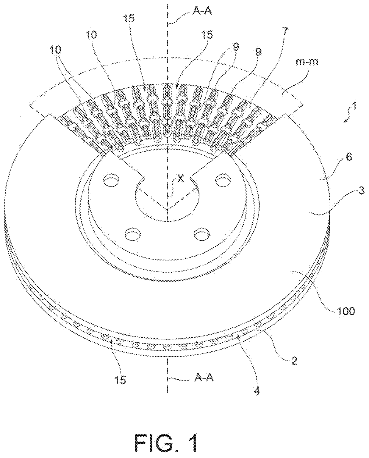
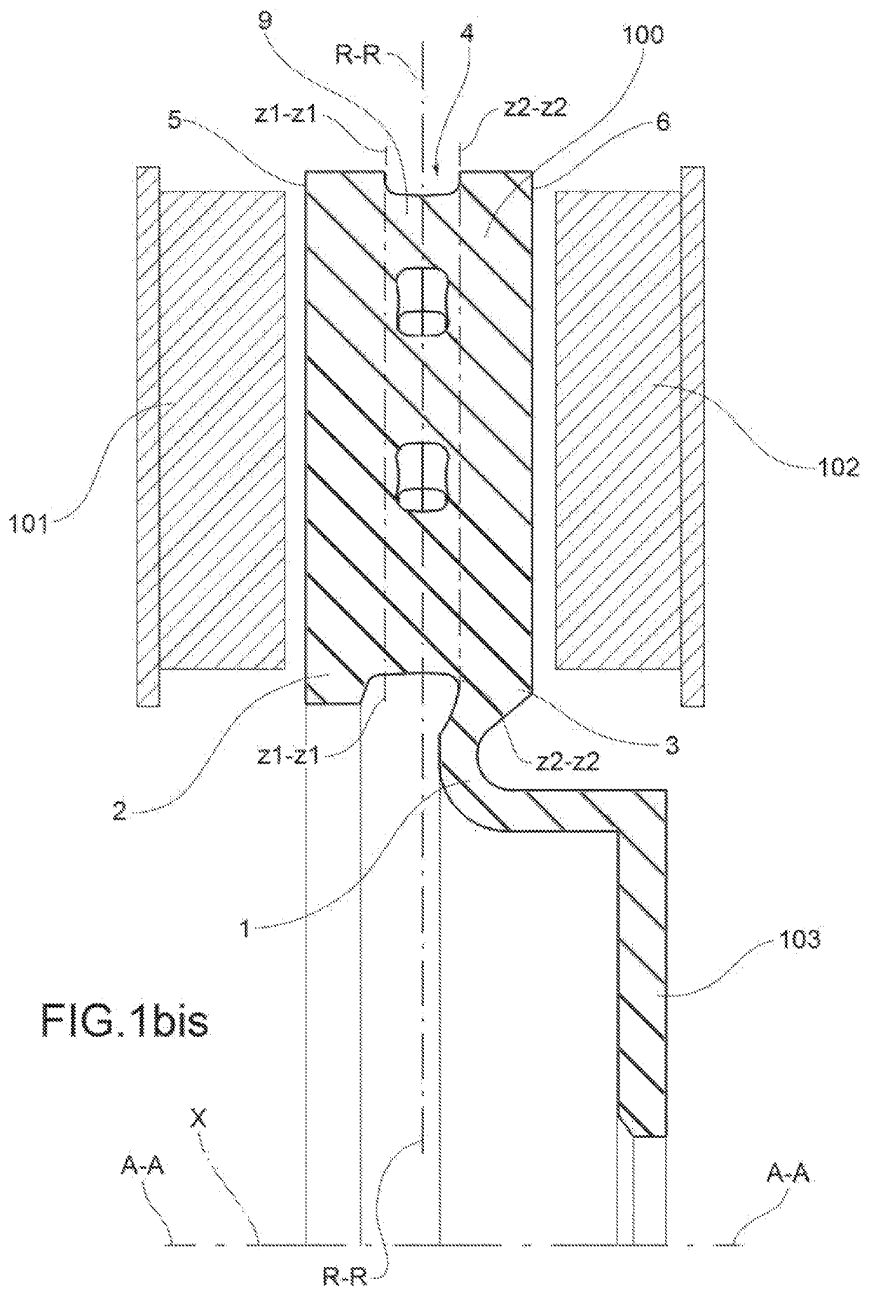
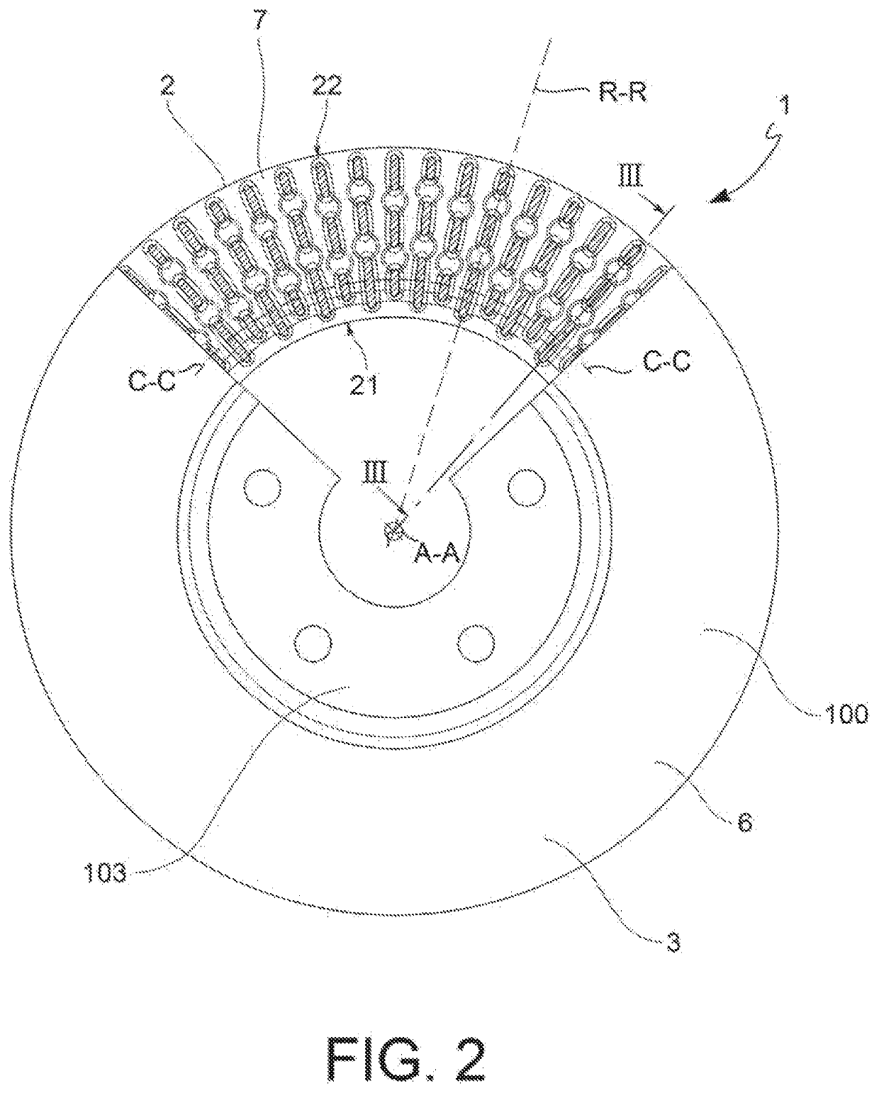
[0033]With reference to the accompanying figures, numeral 100 indicates a ventilated braking band for brake disc as a whole.

[0034]A brake disc defines an axial direction A-A coinciding with the rotation axis X of the brake disc, a radial direction R-R orthogonal to the axial direction A-A, and a tangential C-C or circumferential direction C-C orthogonal to both the axial direction A-A and the radial direction R-R.

[0035]According to a general embodiment, a ventilated braking band 100 comprises a first plate 2 and a second plate 3, which are coaxial to the same axial direction A-A.

[0036]According to one embodiment, at least one between said first plate 2 and said second plate 3 is adapted to be connected to a disc bell which can be associated with the ventilated braking band 100. By way of non-limiting example, according to one embodiment shown in FIG. 1bis, the second plate 3 is connected to the disc bell 103 which can be associated with the ventilated braking band 100.

[0037]Said fir...


PUM


Abstract

A ventilated braking band for brake disc having a first plate and a second plate; the first plate has at least a first inner surface, and the second plate has a second inner surface. The first inner surface defines a first inner surface plane or level (z1-z1) coinciding with said first inner surface, and the said second inner surface defines a second inner surface plane or level (z2-z2) coinciding with the second inner surface. The ventilated braking band has connecting elements which extend in an axial direction between the first inner surface and the second inner surface. The ventilated braking band has at least one bulge. The at least one bulge is partially interpenetrated with: at least one portion of the first foot, thus forming a structural continuity with the first foot, thus avoiding the first inner surface level from being reached; or at least one portion of a second foot, thus forming a structural continuity with the second foot, thus avoiding the second inner surface level from being reached.

Description

FIELD OF THE INVENTION[0001]The present invention relates to a ventilated braking band for a ventilated brake disc, as well as to a ventilated brake disc assembly comprising said ventilated braking band.[0002]The present invention also relates to a method of ventilating a braking band.BACKGROUND ART[0003]In a general brake disc, a system of cylindrical coordinates is generally defined, comprising an axial direction (A-A) coinciding with the rotation axis (X) of the brake disc, a radial direction (R-R) orthogonal to the axial direction, and a tangential or circumferential direction (C-C) orthogonal both to the axial direction (A-A) and to the radial direction (R-R).[0004]Brake discs of the ventilated type are generally known, i.e. comprising a ventilated braking band which comprises two plates on which opposite braking surfaces are obtained being adapted to act in conjunction with opposite brake pads of a brake caliper which can be associated with the brake disc to exert the braking ...

Claims


Application Information

Patent Timeline
Patent Type & Authority Applications(United States)
IPC IPC(8): F16D65/12
CPCF16D65/121F16D2065/1312F16D2065/1308F16D2065/1328F16D65/128
Inventor BIONDO, SIMONEPAGGI, FABRIZIOMEDICI, STEFANODONATI, MICHELE
Owner FRENI BREMBO SPA
Learn More