Transmission belt and continuously variable transmission, method for designing element, and method for producing element

a transmission belt and continuously variable technology, applied in the direction of belts/chains/gearrings, domestic applications, etc., can solve the problem of local wear of the pair of side surfaces, and achieve the effect of reducing local wear

Active Publication Date: 2020-09-24
AISIN CORP +1
View PDF0 Cites 4 Cited by
  • Summary
  • Abstract
  • Description
  • Claims
  • Application Information

AI Technical Summary

Benefits of technology

[0018]The method for producing an element of the present disclosure includes the above-described method for designing an element. Hence, the method for producing an element of the present disclosure can provide the same advantageous effect as the method for designing an element of the present disclosure, i.e., an advantageous effect of being able to reduce local wear of a pair of side surfaces that come into contact with the V-shaped groove of the pulley.

Problems solved by technology

As a result, a bias occurs in contact pressure (surface pressure) between the pair of side surfaces and the pulley, causing local wear of the pair of side surfaces.

Method used


Image

  • Transmission belt and continuously variable transmission, method for designing element, and method for producing element
  • Transmission belt and continuously variable transmission, method for designing element, and method for producing element
  • Transmission belt and continuously variable transmission, method for designing element, and method for producing element

Examples


Embodiment Construction

[0038]Next, modes for carrying out various aspects of the present disclosure will be described with reference to the drawings.

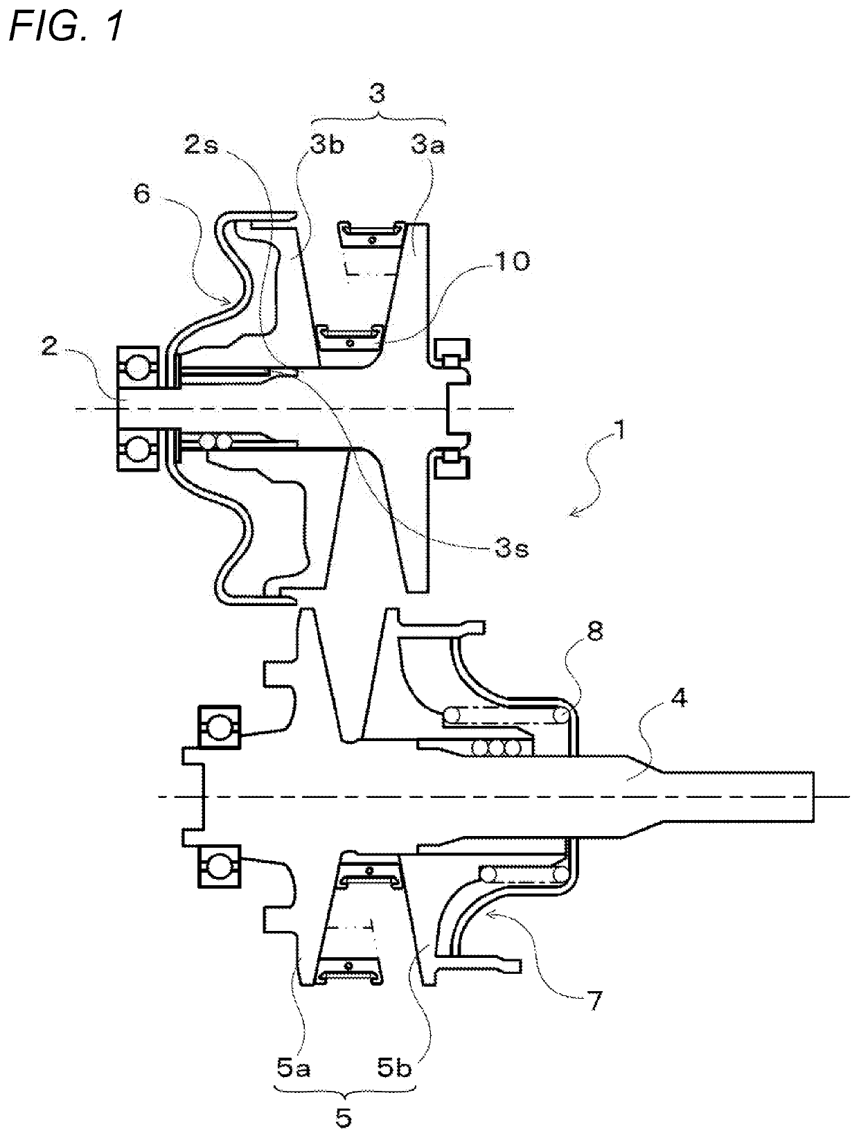
[0039]FIG. 1 is a schematic configuration diagram of a continuously variable transmission 1 of the present embodiment. The continuously variable transmission 1 is mounted on a vehicle and includes, as shown in the drawing, a primary shaft 2 serving as a driving-side rotating shaft; a primary pulley 3 provided on the primary shaft 2; a secondary shaft 4 serving as a driven-side rotating shaft and disposed parallel to the primary shaft 2; a secondary pulley 5 provided on the secondary shaft 4; and a transmission belt 10 wound around a pulley groove (V-shaped groove) of the primary pulley 3 and a pulley groove (V-shaped groove) of the secondary pulley 5.

[0040]The primary shaft 2 is coupled through a forward / reverse switching mechanism (not shown) to an input shaft (not shown) coupled to a power source such as an engine (internal combustion engine). The primary p...


PUM


Abstract

Elements of a transmission belt wound around pulleys of a continuously variable transmission each include a body part, a pair of pillar parts, and a pair of side surfaces. The pair of side surfaces each include a first side surface formed on a corresponding one of the pillar parts; and a second side surface formed so as to continue from the first side surface, and located more on an inner circumference side than the first side surface. A pair of the first side surfaces each are formed so as to be inclined toward an inner side of a corresponding one of the pillar parts with respect to an extending direction, from an inner circumference side to an outer circumference side of a ring, of a corresponding one of the second side surfaces continuing from the first side surface, and a pair of the second side surfaces is formed such that the second side surfaces are spaced farther apart from each other as the second side surfaces extend from the inner circumference side to the outer circumference side, and that an angle formed between the pair of the second side surfaces is larger by 0.2 to 0.8 degrees than an opening angle of V-shaped grooves of the pulleys.

Description

CROSS REFERENCE TO RELATED APPLICATIONS[0001]This application is a National Stage of International Application No. PCT / JP2018 / 045014 filed Dec. 7, 2018 claiming priority based on Japanese Patent Application No. 2017-235552, filed Dec. 7, 2017, the entire contents of which are incorporated herein by reference.TECHNICAL FIELD[0002]The present specification discloses a transmission belt, a continuously variable transmission, a method for designing an element, and a method for producing an element.BACKGROUND ART[0003]Conventionally, as a transmission belt of this kind, there is proposed a transmission belt that includes a plurality of elements each including a main body part (body part) including a saddle surface, and column parts (pillar parts) extending from both sides in a width direction of the saddle surface in the width direction; and a ring that circularly puts together the plurality of elements by an inner circumferential surface of the ring coming into contact with each of the ...

Claims


Application Information

Patent Timeline
Patent Type & Authority Applications(United States)
IPC IPC(8): F16G5/16F16H9/18B21D53/14
CPCB21D53/14F16H9/18F16G5/16F16H9/12
Inventor OCHI, AKIRAURATA, RYOHEIISHIHARA, WATARUTOKUNAGA, JUNICHIMIYAKE, TAKAYUKITAKAHARA, HIDEAKININOMIYA, KEISUKEINASE, YUKAJI, FUMIYANAGASAWA, YUJI
Owner AISIN CORP
Why Eureka
Try Eureka