
Touchpad module and computing device using same

a technology of touch control and computing device, which is applied in the field of input devices with touch control functions, can solve the problems of the inability to adjust the upward/downward swinging action of the touch member, etc., and achieve the effect of increasing the swinging stability of the touch member

Active Publication Date: 2020-09-24
PRIMAX ELECTRONICS LTD
View PDF0 Cites 2 Cited by
  • Summary
  • Abstract
  • Description
  • Claims
  • Application Information

AI Technical Summary

Benefits of technology

The present invention provides a touchpad module with a mechanism for increasing the swinging stability of a touch member. When the external force exerted on the touchpad module is eliminated, the swinging structure is swung away from the base plate by using the bending line as the fulcrum in response to a restoring force of the sheet-like elastic element. This ensures that the switch is separated from the triggering part. The elastic element of the touchpad module is the sheet-like elastic element with plural vacant spaces that are discretely arranged. The first adhesive layer matches the shape of the swinging structure. This structural design enhances the tactile feel of operating the touchpad module and the overall structural strength with a simple and easy process of assembly at a reduced fabricating cost.

Problems solved by technology

Recently, the storage capacity and the processor's computing performance for these electronic devices are largely enhanced, and thus their functions become more powerful and complicated.
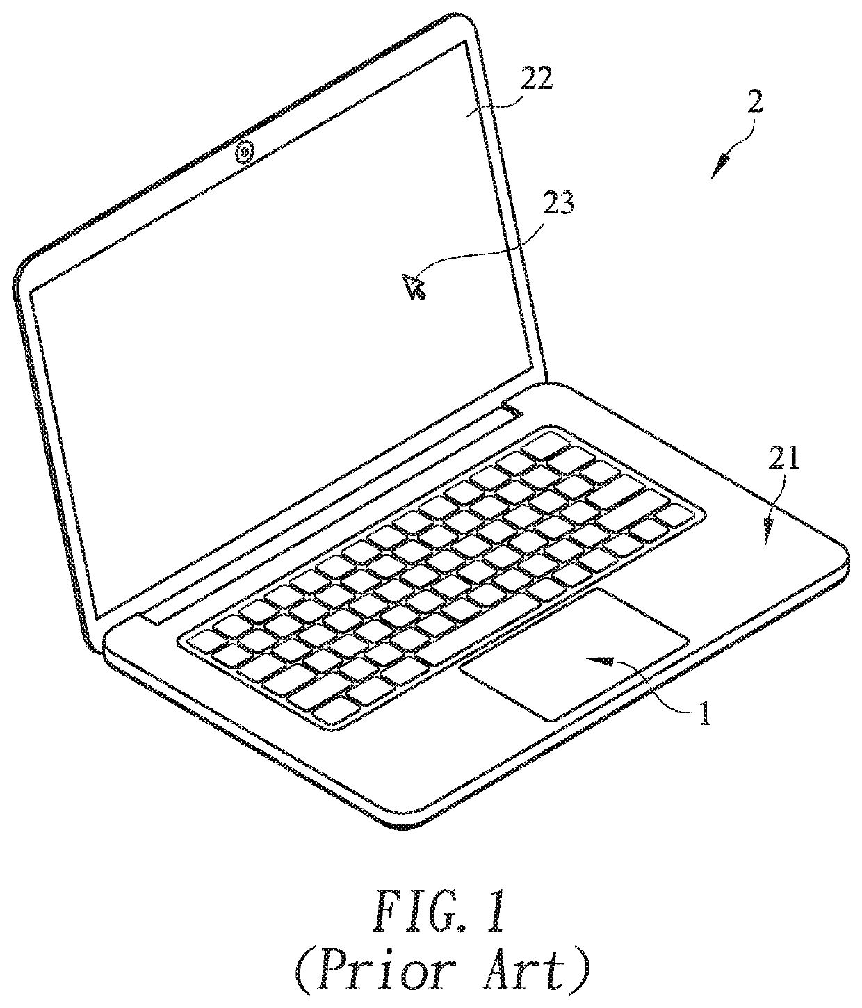
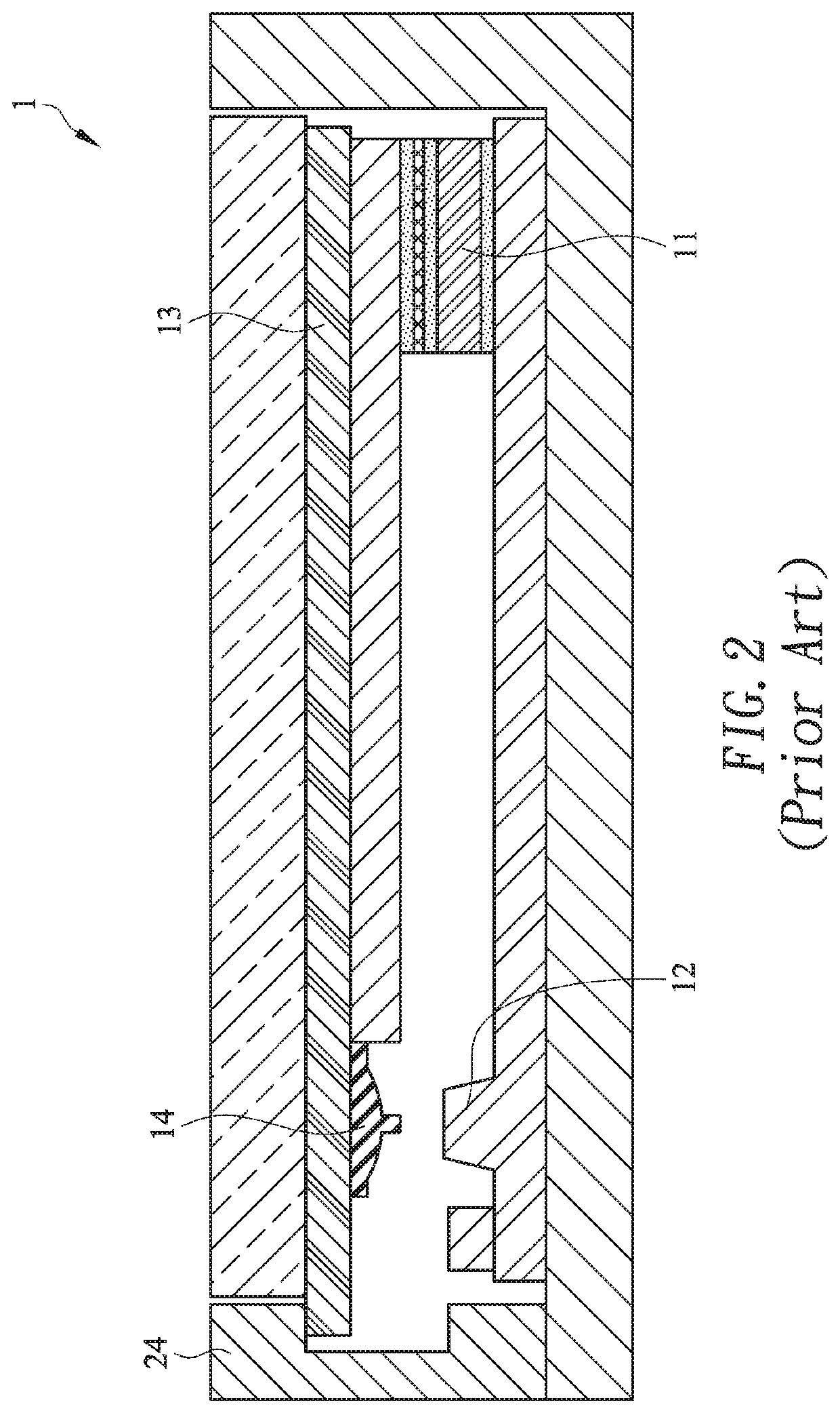
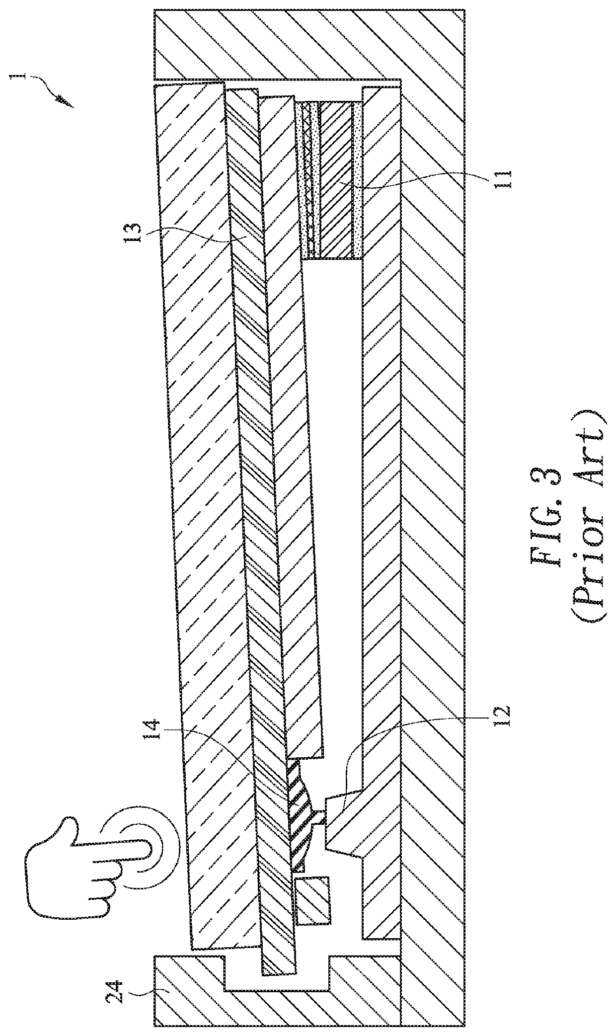
However, the conventional touchpad module 1 still has some drawbacks.
Due to the design of the supporting structure 11, the upward / downward swinging action of the touch member 13 is usually aslant and unstable.

Method used


Image

  • Touchpad module and computing device using same
  • Touchpad module and computing device using same
  • Touchpad module and computing device using same

Examples


Embodiment Construction

[0034]FIG. 4 is a schematic perspective view illustrating the outer appearance of a computing device with a touchpad module according to an embodiment of the present invention. An example of the computing device 4 includes but is not limited to a notebook computer. In an embodiment, the computing device 4 comprises a casing 41, a display screen 42, a processor 45 and a touchpad module 3. The processor 45 is disposed within the casing 41. Moreover, the processor 41 is used for processing electronic signals of the computing device 4. Moreover, a fixing frame 44 is concavely formed in the casing 41 (see FIG. 5). The touchpad module 3 is disposed within the fixing frame 44 and electrically connected with the processor 45. In addition, at least a portion of the touchpad module 3 is exposed outside so as to be touched by the user's finger. Consequently, the user may operate the touchpad module 3 to control the computing device 4. For example, in case that the user's finger is placed on th...


PUM


Abstract

A touchpad module includes a touch member, a base plate, a switch, a supporting structure and a sheet-like elastic element. The base plate includes a triggering part. The switch is disposed on the touch member and aligned with the triggering part. The supporting structure is arranged between the base plate and the touch member. The sheet-like elastic element is located under the touch member and extended along an extension direction. The sheet-like elastic element includes plural vacant spaces. The plural vacant spaces are discretely arranged along the extension direction. The sheet-like elastic element is divided into a swinging structure and plural fixing structures by the plural vacant spaces. In response to an external force, the touch member is swung toward the base plate by using the supporting structure as a fulcrum, and the swinging structure is swung toward the base plate.

Description

FIELD OF THE INVENTION[0001]The present invention relates to an input device, and more particularly to an input device with a touch control function.BACKGROUND OF THE INVENTION[0002]With increasing development of science and technology, a variety of electronic devices are designed in views of convenience and user-friendliness. For helping the user well operate the electronic devices, the electronic devices are gradually developed in views of humanization. The common electronic devices include for example notebook computers, mobile phones, satellite navigation devices, or the like. Recently, the storage capacity and the processor's computing performance for these electronic devices are largely enhanced, and thus their functions become more powerful and complicated. For efficiently operating an electronic device, a touchpad is used as an input device of the electronic device for controlling the operations of the electronic device.[0003]FIG. 1 schematically illustrates a conventional n...

Claims


Application Information

Patent Timeline
IPC IPC(8): G06F1/16H01H21/24H01H21/12G06F3/0354
CPCG06F3/03547H01H21/24G06F1/169H01H21/12G06F1/1616G06F2203/04105
Inventor HUANG, TAI-SOUYEN, SHAO-JU
Owner PRIMAX ELECTRONICS LTD
Learn More