
Touch electrode and touch display device

a touch electrode and display device technology, applied in the field of display technologies, can solve the problems of in-cell touch technology sensitivity, current touch electrodes, high cost and limitation of product thinning, etc., to improve product stability, improve display effect, and reduce the length of connecting bridge

Active Publication Date: 2021-07-20
WUHAN CHINA STAR OPTOELECTRONICS SEMICON DISPLAY TECH CO LTD
View PDF2 Cites 0 Cited by
  • Summary
  • Abstract
  • Description
  • Claims
  • Application Information

AI Technical Summary

Benefits of technology

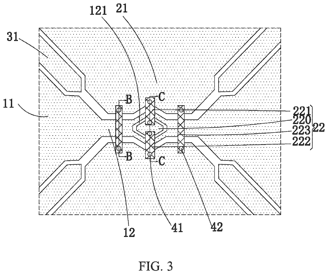
The present invention is a touch electrode and a touch display device that can reduce connection defects and improve product stability. The touch electrode has multiple first electrodes and second electrodes that are insulated from each other, and the second electrodes are connected through a connecting island and bridges. This design reduces the length of the connecting bridge, which prevents the connection from breaking and improves the product stability and display quality. The touch display device can reduce connection defects, increase touch stability, and improve display quality.

Problems solved by technology

However, due to factors, such as higher technical difficulty and being susceptible to signal interference, the sensitivity of the in-cell touch technologies is generally poor.
Advantages of the external mounting touch display panels include high sensitivity and fast response speed, but there are also disadvantages including high cost and limitation on product thinning.
However, the current touch electrodes have the following problems.
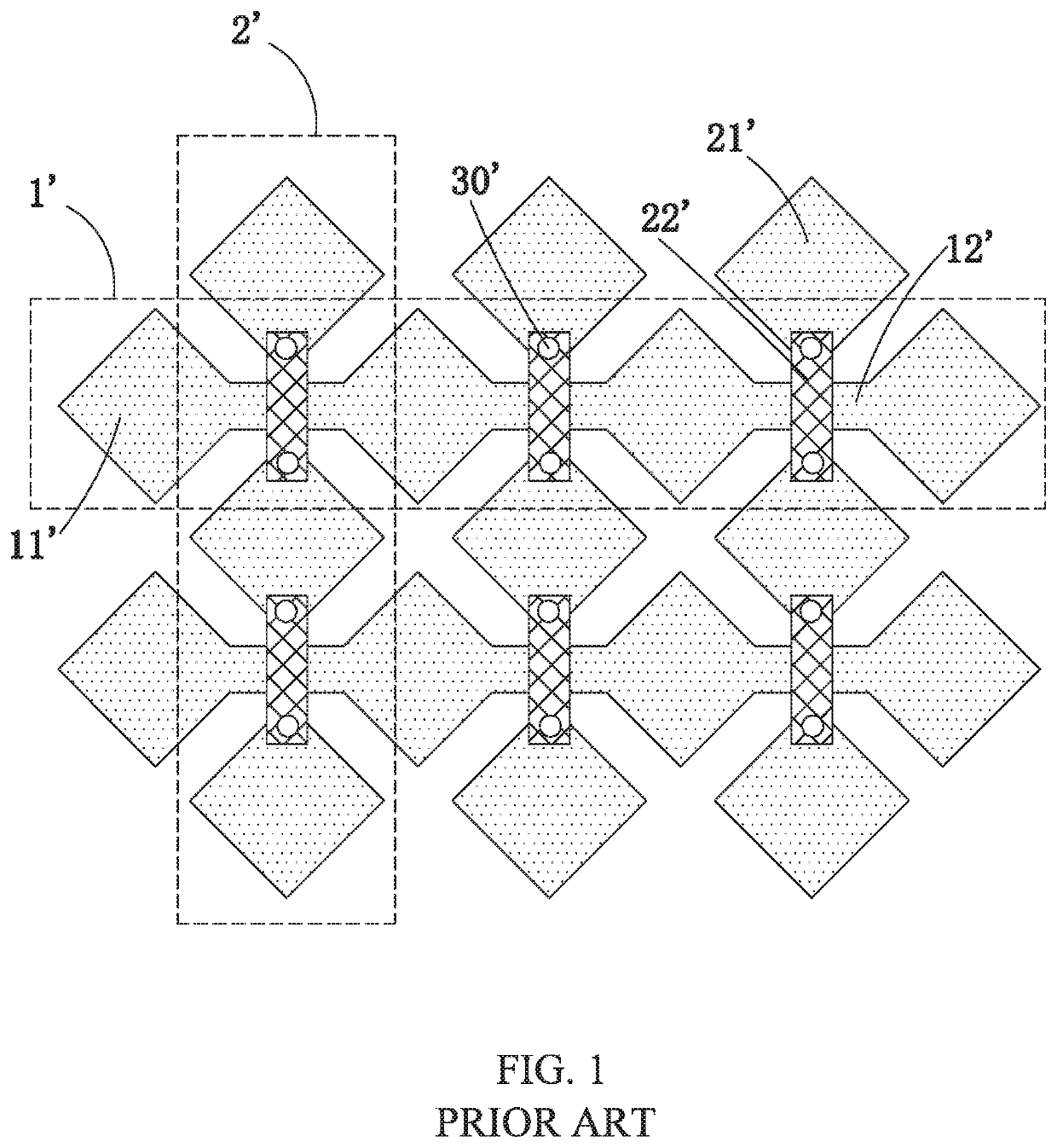
Thus, in an actual process, the connecting position would blacken or brighten to lower the display quality due to the excessively long length of the second connecting line 22′.
However, the broken line, electrical breakdown, and other defects of the second connecting line 22′ with the long length are likely to occur in an actual process, thus resulting in touch failure.

Method used


Image

  • Touch electrode and touch display device
  • Touch electrode and touch display device
  • Touch electrode and touch display device

Examples


Embodiment Construction

[0026]In order to further elaborate the technical means and effects adopted by the present invention, the present invention will be further described in detail with the preferred embodiments and the accompanying drawings.

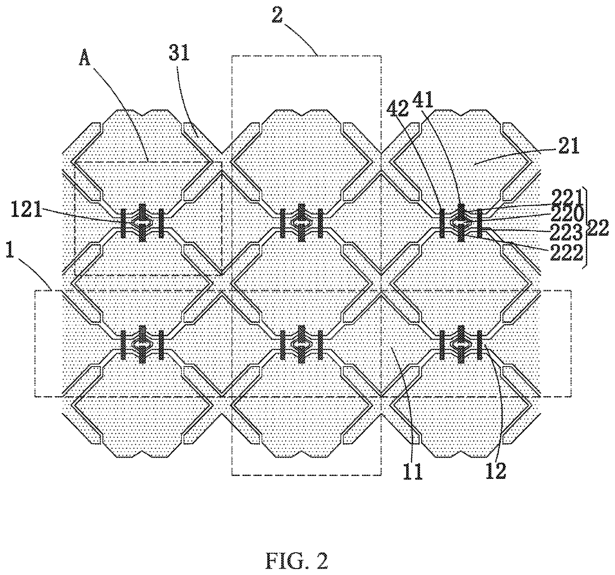
[0027]Please refer to FIG. 2 to FIG. 5, the present invention provides a touch electrode including a plurality of mutually parallel and separated first electrode chains 1 and a plurality of mutually parallel and separated second electrode chains 2 configured to intersect with the first electrode chains 1 and to be insulated from the first electrode chains 1.

[0028]Each of the first electrode chains 1 comprises a plurality of mutually separated first electrodes 11 and a first connecting portion 12 located at an intersection of the first electrode chains 1 and the second electrode chains 2, and the two adjacent first electrodes 11 are electrically connected through the first connecting portion 12.

[0029]Each of the second electrode chains 2 comprises a plurality of mutu...


PUM

PropertyMeasurementUnit
areaaaaaaaaaaa
electricallyaaaaaaaaaa
insulatingaaaaaaaaaa

Abstract

Disclosed is a touch electrode and a touch display device. The touch electrode comprises a plurality of first electrode chains and second electrode chains intersecting with the first electrode chains. Each of the first electrode chains comprises a plurality of first electrodes and a first connecting portion. Each of the second electrode chains comprises a plurality of second electrodes and a second connecting portion. Each of the second connecting portions comprises a connecting island located between the two adjacent second electrodes, at least one first connecting bridge electrically connecting the connecting island and one of the two adjacent second electrodes and at least one second connecting bridge electrically connecting the connecting island and the other of the two adjacent second electrodes. By means of the present invention, the length of the connecting bridge can be reduced and the breaking of the connection can be prevented.

Description

FIELD OF INVENTION[0001]The present invention relates to the field of display technologies, and in particular, to a touch electrode and a touch display device.BACKGROUND OF INVENTION[0002]With development of display technologies, flat-panel display devices, such as liquid crystal display (LCD) devices are widely employed in various consumer electronics, such as mobile phones, televisions, personal digital assistants, digital cameras, notebook computers, desktop computers, and so on due to their high definition, power saving, thin body, and a wide range of application, becoming the mainstream of the display devices.[0003]A touch panel provides a new human-computer interaction interface which is more direct and user-friendly in use. The touch panel and the flat display device are integrated to form a touch display device, which can enable the flat display device to have a touch function to perform input by a finger, a stylus, and so on so that the operation is more intuitive and simpl...

Claims


Application Information

Patent Timeline
Patent Type & Authority Patents(United States)
IPC IPC(8): G06F3/044G06F3/041
CPCG06F3/0446G06F3/0412G06F2203/04111G06F3/044
Inventor DENG, YICHAODAI, QIBINGMA, YALONG
Owner WUHAN CHINA STAR OPTOELECTRONICS SEMICON DISPLAY TECH CO LTD
Learn More