A combined surface acoustic wave touch screen

A surface acoustic wave and touch screen technology, applied in the field of combined surface acoustic wave touch screens, can solve the problems of surface acoustic wave signal deterioration, reflection stripe array deformation, easy accumulation of dust, etc., to improve safety, reduce the loss of acoustic wave signals, and improve stability. sexual effect

Active Publication Date: 2016-07-13
GENERALTOUCH TECH
View PDF3 Cites 0 Cited by
  • Summary
  • Abstract
  • Description
  • Claims
  • Application Information

AI Technical Summary

Problems solved by technology

[0005] However, the existing technology represented by the above-mentioned patent documents still has the following defects in the actual production and use process: 1. Although the patent realizes the acoustic wave touch screen with zero frame, because the reflective stripe array is arranged on the touch surface, this The touch surface is not a complete pure plane, resulting in poor aesthetics of the touch screen; two, because the reflective stripe array is set on the touch surface, it is easy to accumulate dust, and it is not convenient for maintenance and cleaning; three, because the transducer is set on a smooth transition surface 4. In this patent, both the reflective stripe array and the transducer are arranged on the touch substrate. The stripe array must also be baked at high temperature, which will easily lead to deformation of the reflective stripe array, resulting in the deterioration of the surface acoustic wave signal, and is not conducive to the intensive and high-efficiency production of acoustic wave components; 5. The printing of the reflective stripe array of the surface acoustic wave touch screen adopts Screen printing, and the existing screen printing technology requires that the printing surface (the surface where the stripes are set) must be flat and the printing surface and the touch surface must be on the same plane, or the back of the touch surface must be on the same plane, resulting in narrower borders , Boundless, lightweight, elegant, special-shaped and other requirements and the surface acoustic wave screen silk screen processing technology can not meet the contradictions, which also lead to the limitation of the surface acoustic wave touch screen processing technology and development

Method used


Image

  • A combined surface acoustic wave touch screen
  • A combined surface acoustic wave touch screen
  • A combined surface acoustic wave touch screen

Examples


Embodiment 1

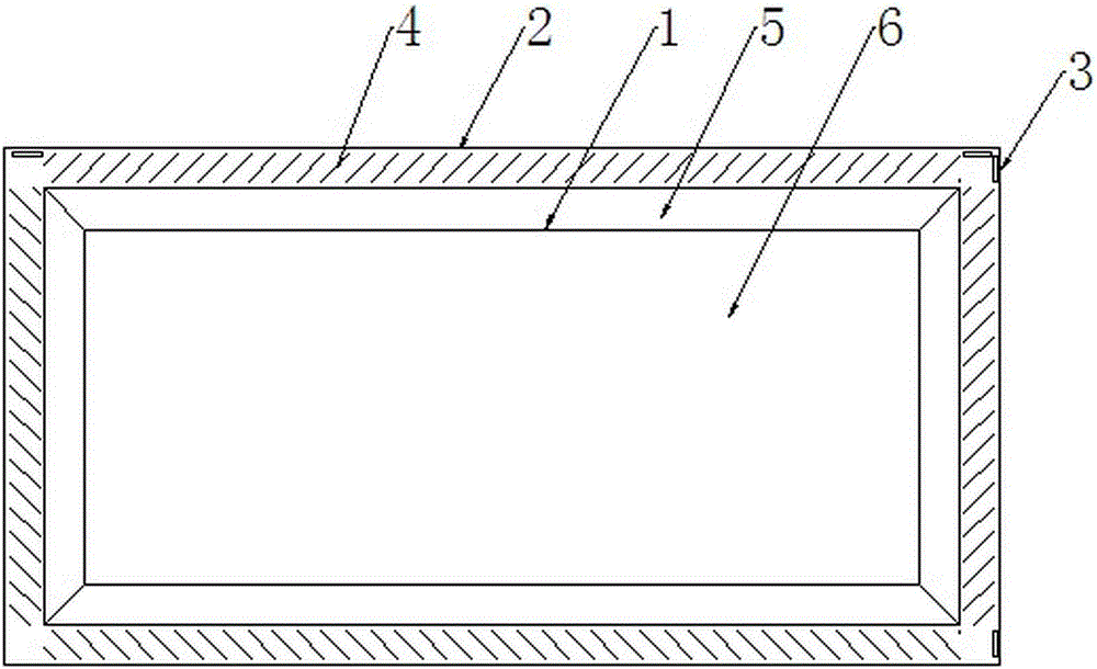
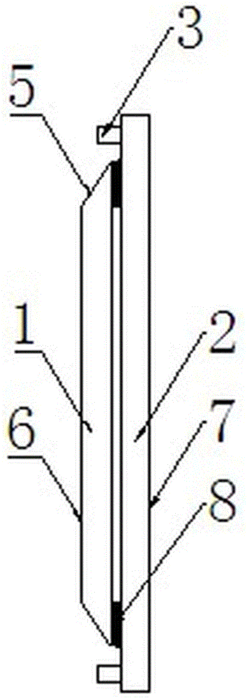
[0045] A combined surface acoustic wave touch screen, including a touch substrate 1, a reflective stripe array 4 and a transducer 3, and also includes an acoustic wave component substrate 2, the reflective stripe array 4 and the transducer 3 are fixedly arranged on the acoustic wave component substrate 2, the acoustic wave component substrate 2 is fixedly connected to the touch substrate 1, and the reflective stripe array 4 and the transducer 3 cooperate on the front surface 6 of the touch substrate 1 to form matrix acoustic signals.

[0046] In this embodiment, the four sides of the touch substrate 1 are preferably set as smooth transition surfaces 5, so that when the surface acoustic wave signal is transmitted between different substrates or between different surfaces of the same substrate, the loss of the acoustic wave signal is smaller .

[0047] Further, when the frame size of the acoustic wave component base material 2 is larger than the frame size of the touch base mate...

Embodiment 2

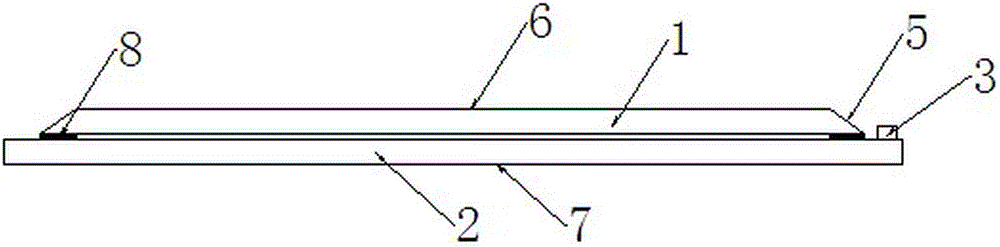
[0049] This embodiment is basically the same as Embodiment 1, the main difference is: when the frame size of the acoustic wave component substrate 2 is larger than the frame size of the touch substrate 1, the four sides of the acoustic wave component substrate 2 are smooth transition surfaces 5 The touch base material 1 is fixedly stacked on the front side 6 of the acoustic wave component base material 2 , and the reflective stripe array 4 and the transducer 3 are fixedly arranged around the back surface 7 of the acoustic wave component base material 2 at this time.

Embodiment 3

[0051] This embodiment is basically the same as Embodiment 1, the main difference is that: when the frame size of the acoustic wave component base material 2 is the same as that of the touch base material 1, the touch base material 1 is fixed on the front side of the acoustic wave component base material 2 6. At this time, the reflective stripe array 4 and the transducer 3 are fixedly arranged around the front 6 or the back 7 of the acoustic wave component substrate 2 .

[0052] Further, the reflective stripe array 4 and the transducer 3 are preferably arranged around the front surface 6 of the acoustic wave component substrate 2 .


PUM


Abstract

The invention discloses a combined surface sound wave touch screen, comprising a touch base material, a reflecting stripe array, a transducer and a sound wave component base material, wherein the reflecting strip array and the transducer are fixedly arranged on the sound wave component base material; the sound wave component base material is fixedly connected with the touch base material; and the reflecting strip array and the transducer are matched on the front side of the touch base material to form a matrix sound wave signal. By adoption of the combined surface sound wave touch screen, a touch surface is separated from a sound wave component, so that the touch surface forms an integrated flat surface and a zero frame structure of the surface sound wave touch screen is realized; safety, explosion-proof performance, dustproof performance and waterproof performance of the sound wave touch screen can be improved and the touch screen is protected from external disturbance; and the predicament that the sound wave component must be arranged on the same touch base material is solved, so that the development of the surface sound wave touch screen is not limited.

Description

technical field [0001] The invention relates to a surface acoustic wave touch screen, in particular to a combined surface acoustic wave touch screen. Background technique [0002] A common surface acoustic wave touch screen is composed of a screen body, a transmitting / receiving transducer, a reflective stripe array and a signal line. Usually, the reflective stripe array and the transducer are arranged on the touch surface of the screen body, and the transducer and the reflective stripe array will Occupies a certain position, which leads to a thicker frame thickness of the acoustic wave touch screen, which cannot meet the increasingly higher requirements of users. [0003] In order to solve the above problems, the following technologies have been proposed in the prior art: [0004] For example, Chinese Patent No. "201120234483.3" discloses a surface acoustic wave touch screen with a hidden transducer. A stripe array, a touch area and a transducer, the stripe array and the t...

Claims


Application Information

Patent Timeline
Patent Type & Authority Patents(China)
IPC IPC(8): G06F3/043
Inventor 罗琳
Owner GENERALTOUCH TECH
Why Eureka
Try Eureka