Method for operating a piston compressor, and piston compressor

Pending Publication Date: 2020-10-01
LINDE GMBH
View PDF5 Cites 2 Cited by
  • Summary
  • Abstract
  • Description
  • Claims
  • Application Information

AI Technical Summary

Benefits of technology

[0008]The invention relates to a method for operating a piston compressor having a reciprocating piston in a cylinder, wherein an inlet valve and an outlet valve (or a suction valve and a pressure valve) are provided in the cylinder on the side of a medium to be compressed and conveyed (i.e., in the cylinder head). With a hydraulic drive, which comprises a hydraulic piston, the reciprocating piston is moved to and fro (or up and down) with the use of a hydraulic medium in a first volume, with which the reciprocating piston is loaded on the side of the hydraulic drive.
[0009]The hydraulic piston oscillates in the cylinder between two reversal points—the so-called bottom dead center (BDC) and the so-called top dead center (TDC). When moving in the direction of the top dead center, medium present in the cylinder or cylinder head is compressed and then discharged through the outlet valve; when moving in the direction of the bottom dead center, medium is drawn in through the inlet valve.
[0010]In principle, the reciprocating piston would be moved synchronously with the hydraulic piston in this case. However, due to leakage effects in the circuit of the hydraulic medium (i.e., the first volume mentioned), it may happen that the reciprocating piston is no longer moved synchronously with the hydraulic piston. This means that, for example, at the bottom dead center, the reciprocating piston strikes the cylinder bottom, but the hydraulic piston moves further downward. This produces a negative pressure in the first volume or in the hydraulic circuit. The reciprocating piston can also strike the cylinder head, while the hydraulic piston moves further upward. Thi

Problems solved by technology

The reduction of this dead space reduces the re-expansion of the remaining medium and thereby increases the delivery volume or the efficiency of the compression process.
What results, disadvantageously, are the additional component loads and thereby increased sound emissions due to the characteristic similar to a liquid st

Method used


Image

  • Method for operating a piston compressor, and piston compressor

Examples


Example

DETAILED DESCRIPTION OF THE DRAWING

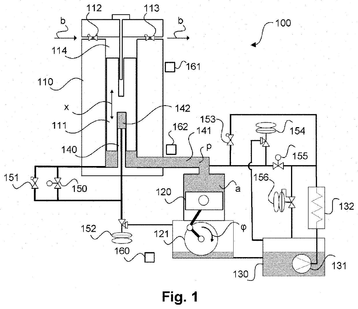
[0026]FIG. 1 schematically shows a piston compressor 100 according to the invention in a preferred embodiment which is suitable for carrying out a method according to the invention.

[0027]The piston compressor 100, also referred to as a reciprocating piston compressor in the form shown, comprises a cylinder 110 in which a reciprocating piston 111 can be moved to and fro or up and down. In principle, such a piston compressor may be multi-stage, i.e., several of the cylinders 110 shown with reciprocating pistons 111 may be present. The following description relating to the cylinder with a reciprocating piston then applies accordingly also to further cylinders with reciprocating pistons.

[0028]The piston compressor 100 is driven by a hydraulic drive, which here comprises a hydraulic piston 120. The hydraulic piston 120 is driven by a rotary wheel with shaft 121 with suitable linkage (hydraulic crank drive). Rotation of this shaft 121, as indicated by an...


PUM


Abstract

The invention relates to a method for operating a piston compressor (100) having a reciprocating piston (111) in a cylinder (110), wherein an inlet valve (112) and an outlet valve (113) are provided in the cylinder (110) on the side of a medium (b) which is to be compressed and conveyed, wherein the reciprocating piston (111) is moved to and fro by way of a hydraulic drive (120, 121) with a hydraulic piston (120) with the use of a hydraulic medium (a) in a first volume (141), with which the reciprocating piston (111) is loaded on the side of the hydraulic drive (120, 121), wherein, if required, hydraulic medium (a) is fed into the first volume (141) and/or is discharged from the first volume (141) in a manner which is dependent on a position of the hydraulic piston (120) and/or a rotational angle ((p) of a shaft (121) which is provided for moving the hydraulic piston (120) in relation to a position (x) of the reciprocating piston (120) and/or a pressure (p) in the first volume (141), and to a piston compressor (100) of this type.

Description

[0001]The invention relates to a method for operating a piston compressor and to a piston compressor.[0002]Compressors are used in particular for compressing gaseous media. The efficiency of conventional piston compressors is very strongly influenced by the presence of residual volume or dead space in the top dead center. Gas or medium in this region leads to a re-expansion and a reduction in the inflowing delivery volume possible in the suction cycle. This region is unavoidable, in order to compensate for manufacturing tolerances and thermal expansions of the components, and to subsequently avoid mechanical contact of the reciprocating pistons with the cylinder head in the compressor. Channels for the suction and pressure valves (i.e., inlet and outlet valves) increase this negative effect.[0003]The reduction of this dead space reduces the re-expansion of the remaining medium and thereby increases the delivery volume or the efficiency of the compression process. So-called ionic com...

Claims


Application Information

Patent Timeline
IPC IPC(8): F04B49/16F04B25/00
CPCF04B25/005F04B2201/0808F04B2201/0201F04B49/16F04B2201/0206F04B9/10F04B35/04F04B39/0027F04B39/0005F04B39/12F04B39/10F05B2210/12F05B2260/96F04B1/02F04B9/109F04B19/22F04B27/005F04B49/002F04B49/08F04B49/22F04B53/10F04B9/107
Inventor DORNER, SASCHANAGL, CHRISTOPHFRITZER, JOHANNESFISCHER, KLAUS
Owner LINDE GMBH
Why Eureka
Try Eureka