Eureka AIR delivers breakthrough ideas for toughest innovation challenges, trusted by R&D personnel around the world.

Damper housing for vehicle

a technology for a vehicle and a housing is applied in the field of adamper housing, which can solve the problems of increasing the weight of the vehicle, the difficulty of efficiently distributing and supporting a large load, and the increase of product costs, so as to minimize twisting, minimize the collapse region, and minimize the effect of twisting

Active Publication Date: 2020-10-08
HONDA MOTOR CO LTD
View PDF0 Cites 2 Cited by
  • Summary
  • Abstract
  • Description
  • Claims
  • Application Information

AI Technical Summary

Benefits of technology

The present invention is about providing a damper housing for a vehicle that can increase the strength of the upper section of the damper. The invention distributes the load from the damper to the reinforcement plate and the wall plate using collars, which ensures even distribution and transmission of the load to a wide range of surfaces. This results in efficient support strength of the upper section of the damper.

Problems solved by technology

For this reason, it is difficult to efficiently distribute and support a large load input from the upper section of the damper to the upper wall of the lower housing and the cover wall of the upper housing, and in order to stably support the input load, it is necessary to increase a thickness of the lower housing or the upper housing.
However, when the thickness of the lower housing or the upper housing is increased, since this tends to cause an increase in vehicle weight and a rise in product costs, it is desired to devise a structure that can more efficiently support a load input from the upper section of the damper.

Method used


Image

  • Damper housing for vehicle
  • Damper housing for vehicle
  • Damper housing for vehicle

Examples


Embodiment Construction

[0035]Hereinafter, embodiments of the present invention will be described with reference to the accompanying drawings. Further, in appropriate places in the drawings, an arrow FR indicates a forward direction with respect to a vehicle 1, an arrow UP indicates an upward direction with respect to the vehicle 1, and an arrow LH indicates a leftward direction with respect to the vehicle 1.

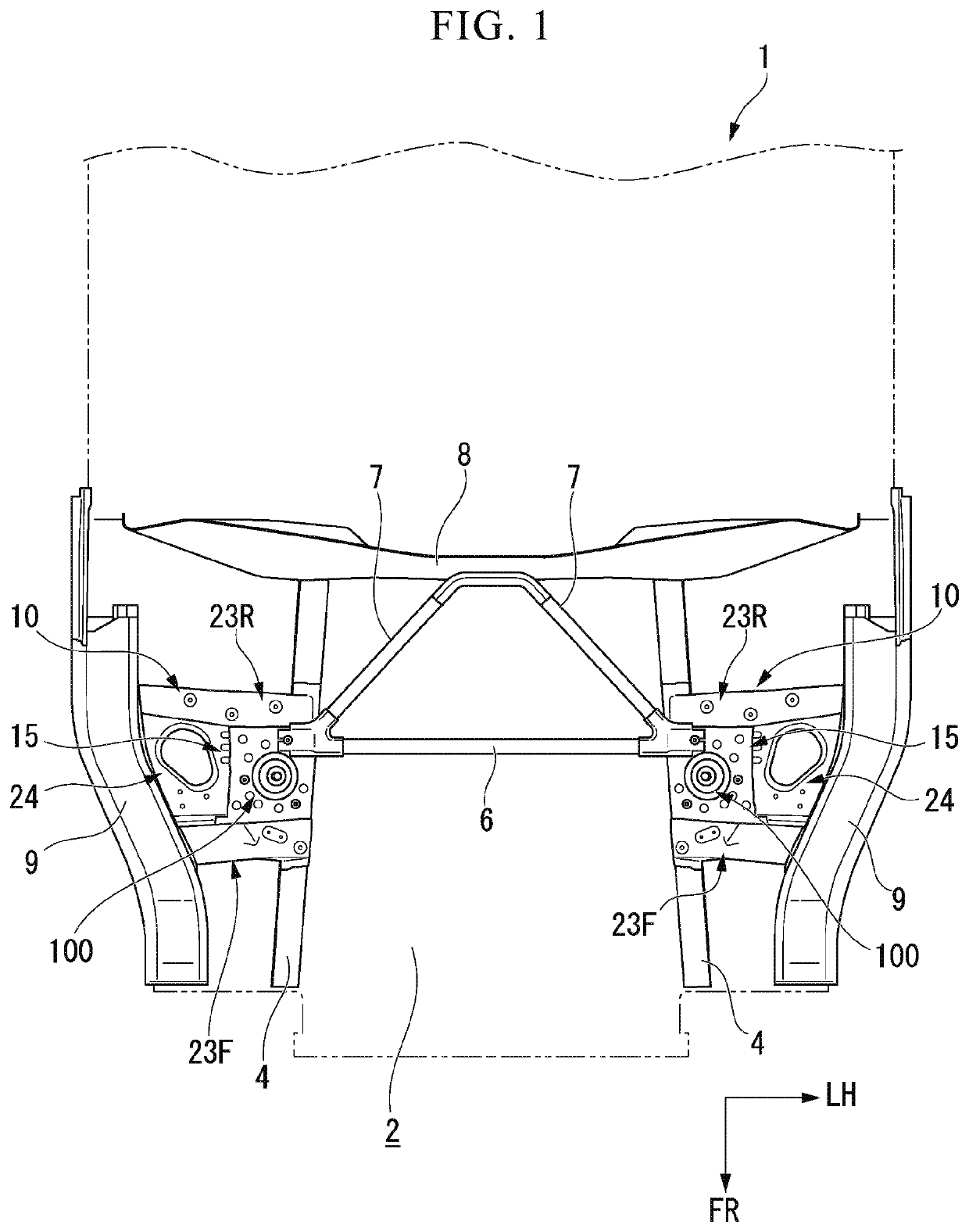
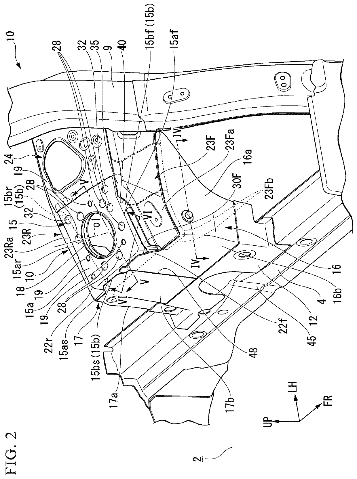
[0036]FIG. 1 is a view showing a skeleton section on a side of a front section of the vehicle 1 of the embodiment from above, and FIG. 2 is a view showing an attachment section of damper housings 10 of the embodiment from above a right front section of the vehicle 1. Further, FIG. 2 shows the damper housing 10 disposed on a left side of the vehicle.

[0037]Reference numeral 2 in the drawings is an engine compartment disposed in front of a passenger compartment. A pair of front side frames 4 extending substantially in a vehicle forward / rearward direction are disposed on both sides of a lower side of the e...


PUM


Abstract

A damper housing includes an upper-wall-plate and an upper-wall-reinforcement-plate. A plurality of collars through which fastening members for attaching a damper are interposed between the upper-wall-plate and the upper-wall-reinforcement-plate. The collars are disposed on a circumference around the damper. An upper section of the damper is fastened and fixed to the upper-wall-reinforcement-plate and the upper-wall-plate by the fastening members. A concave section is formed in at least one of the upper-wall-plate and the upper-wall-reinforcement-plate which are facing each other, the concave section being formed so as to protrude toward the facing upper-wall-plate or the upper-wall-reinforcement-plate. The concave section is disposed between the neighboring collars on the circumference on which the collars are disposed. The upper-wall-plate and the upper-wall-reinforcement-plate are coupled to the facing upper-wall-plate or the upper-wall-reinforcement-plate at the concave section.

Description

CROSS-REFERENCE TO RELATED APPLICATION[0001]Priority is claimed on Japanese Patent Application No. 2019-073101, filed Apr. 5, 2019, the content of which is incorporated herein by reference.BACKGROUND OF THE INVENTIONField of the Invention[0002]The present invention relates to a damper housing for a vehicle configured to support an upper section of a damper of a suspension.Description of Related Art[0003]As a structure of a support section of a suspension of a vehicle, a structure in which an upper end portion of a damper is supported by a damper housing is known. The damper housing is, for example, a structure coupled to a front side frame and an upper member of the vehicle body and configured to support a load input from the damper to the vehicle body. The damper housing has an upper wall section, and an upper end portion of the damper is fastened and fixed to the upper wall section (for example, German Patent Publication No. 102014104838).[0004]The damper housing disclosed in Germ...

Claims


Application Information

Patent Timeline
Patent Type & Authority Applications(United States)
IPC IPC(8): B62D25/08B60G13/00
CPCB62D25/088B60G2204/128B60G13/003B60G2206/41
Inventor YOSHIDA, MASAYASUABE, YUYA
Owner HONDA MOTOR CO LTD
Why Eureka
Eureka Blog
Learn More