
Diaphragm pump

a diaphragm pump and diaphragm technology, applied in the direction of pump parameters, positive displacement liquid engines, instruments, etc., can solve the problem that the diaphragm pump cannot be returned to the origin, and the detection device is unnecessary, so as to reduce manufacturing costs and enhance the discharge accuracy. the effect of fluid transfer

Active Publication Date: 2020-10-08
NIPPON PILLAR PACKING CO LTD
View PDF0 Cites 1 Cited by
  • Summary
  • Abstract
  • Description
  • Claims
  • Application Information

AI Technical Summary

Benefits of technology

The present invention provides a diaphragm pump that can improve the accuracy of fluid transfer while reducing manufacturing costs. This is achieved by improving the diaphragm's ability to return to its original position before the pump is used. Additionally, the detector that helps return the diaphragm to its origin is not necessary, which further lowers costs. Overall, the diaphragm pump can enhance the accuracy of fluid transfer while reducing manufacturing costs.

Problems solved by technology

Further, the detector for returning the diaphragm to the origin is unnecessary.

Method used


Image

  • Diaphragm pump
  • Diaphragm pump
  • Diaphragm pump

Examples


Embodiment Construction

[0022]An embodiment of the present invention will be described with reference to the drawings.

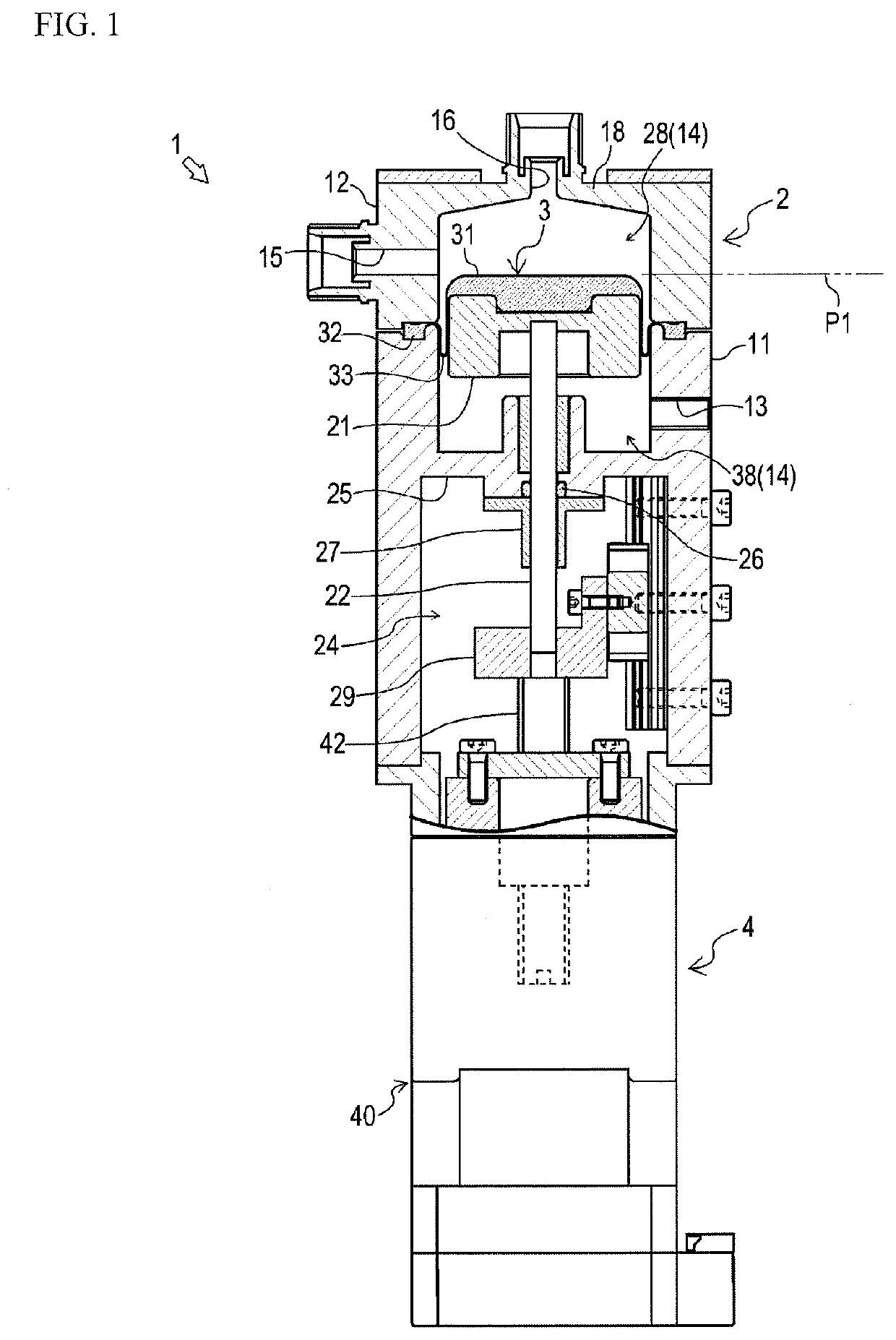
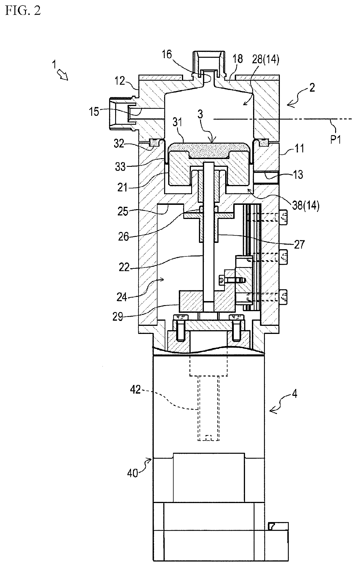
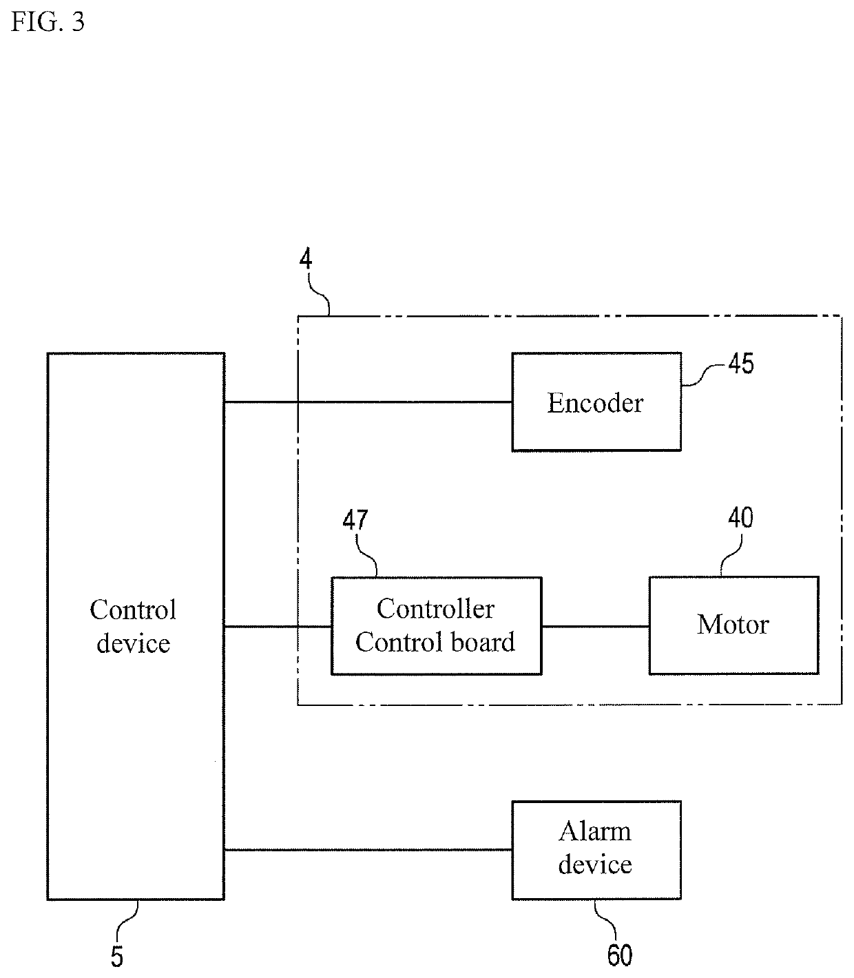
[0023]A diaphragm pump 1 according to the embodiment of the present invention is a volumetric reciprocating pump for transferring fluid such as chemical liquid. As shown in FIGS. 1 and 2, the diaphragm pump 1 includes a housing 2, a diaphragm 3, an actuator 4, and a control device 5.

[0024]In the following description, a back-and-forth direction refers to the vertical direction on the drawings, advance refers to forward movement, and retreat refers to backward movement.

[0025]The housing 2 accommodates a stationary member and a movable member. In the present embodiment, the housing 2 has an internal space, in which the stationary member is disposed and provided to keep stationary with respect to the housing 2. Examples of the stationary member include an O-ring retainer 27 described later.

[0026]The housing 2 includes a cylinder 11 and a pump head 12. The cylinder 11 is made of stainless steel...


PUM


Abstract

A diaphragm pump includes a reciprocable diaphragm, an actuator including a motor, and a control device. The control device resets an origin of the diaphragm in a reciprocating direction, when detecting a step-out of the motor. After resetting the origin, the control device activates the actuator to move the diaphragm to the origin.

Description

TECHNICAL FIELD[0001]The present invention relates to a diaphragm pump.BACKGROUND ART[0002]A diaphragm pump is known as a volumetric reciprocating pump for transferring fluid such as chemical liquid (e.g., see Patent Document 1). The diaphragm pump is often used when a high discharge accuracy is required in fluid transfer, for example, in manufacture of semiconductors, liquid crystals, organic electroluminescence (EL) devices, solar cells, or light-emitting diodes (LED).[0003]The diaphragm pump of this type is provided with a housing, a diaphragm, an actuator, and a detector. The diaphragm is disposed to forma pump chamber in the housing, and reciprocable with respect to an origin to change the volume of the pump chamber.[0004]The actuator is configured to reciprocate the diaphragm. The detector is configured to detect the origin of the diaphragm (a reference position of a piston). For ensuring the discharge accuracy, returning the diaphragm to the origin is performed based on the d...

Claims


Application Information

Patent Timeline
Patent Type & Authority Applications(United States)
IPC IPC(8): F04B49/06F04B43/04
CPCF04B2203/02F04B2201/0209F04B2201/0201F04B43/04F04B49/06F04B43/0081F04B53/16F05B2210/11G08B21/18
Inventor TESHIMA, KAZUKIYOYAMADA, NAOTONARUO, MOTOAKI
Owner NIPPON PILLAR PACKING CO LTD
Learn More