
Glazing assemblies with integrated photovoltaic structure and spacer structures for such glazing assemblies

Inactive Publication Date: 2020-10-08
PHYSEE GRP BV
View PDF5 Cites 7 Cited by
  • Summary
  • Abstract
  • Description
  • Claims
  • Application Information

AI Technical Summary

Benefits of technology

The invention relates to a glazing assembly with photovoltaic cell modules mounted on the peripheral spacer structure which is positioned between the first and second glass panes. The peripheral spacer structure comprises mounting members that tilt the light receiving surface of the PV cells towards the outer glass pane, allowing them to optimally orient towards the sun without affecting the thermal properties of the glazing assembly. The PV cell modules can be mounted on the spacer structure using a mechanical mechanism, such as clamping or sliding, which allows sufficient thermal expansion of the different materials so that deteriorating effects due to thermal stress can be minimized. The technical effect of the invention is to provide a power-generating glazing assembly that optimizes sun-to-cells orientation while maintaining good thermal performance.

Problems solved by technology

Laminating photovoltaic elements against the glass panes in a peripheral area of such window structure does not allow orienting the photovoltaic elements in such as way so that they can be operated in an optimal way.
Further, the lamination of the photovoltaic elements may negatively influence the thermal properties of the window structure.
Additionally, thermal effects may cause stress in the photovoltaic elements affecting its overall performance.
Thus, the suggested PV functionalities of the glazing structures are as such not compatible with the high-volume production processes of modern high-performance multi-pane glazing structures.

Method used


Image

  • Glazing assemblies with integrated photovoltaic structure and spacer structures for such glazing assemblies
  • Glazing assemblies with integrated photovoltaic structure and spacer structures for such glazing assemblies
  • Glazing assemblies with integrated photovoltaic structure and spacer structures for such glazing assemblies

Examples


Embodiment Construction

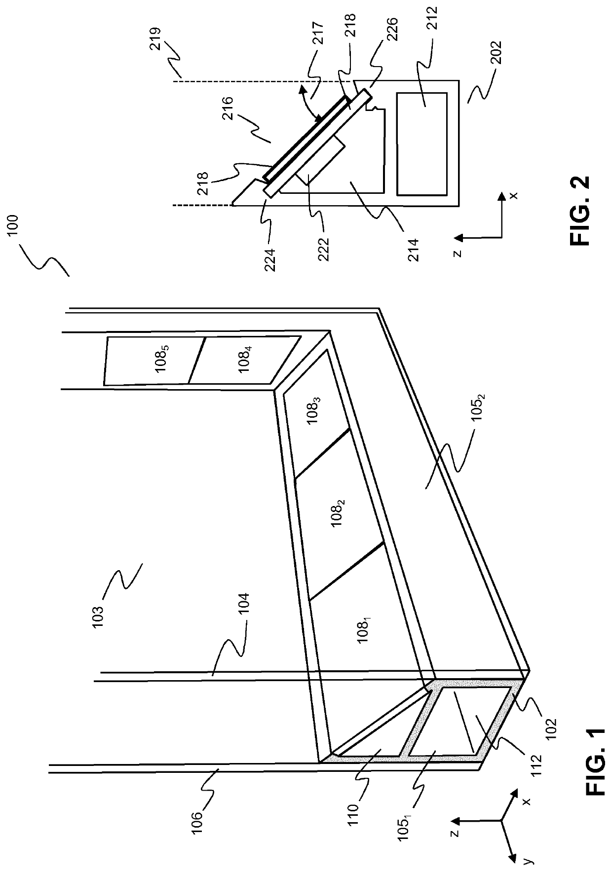
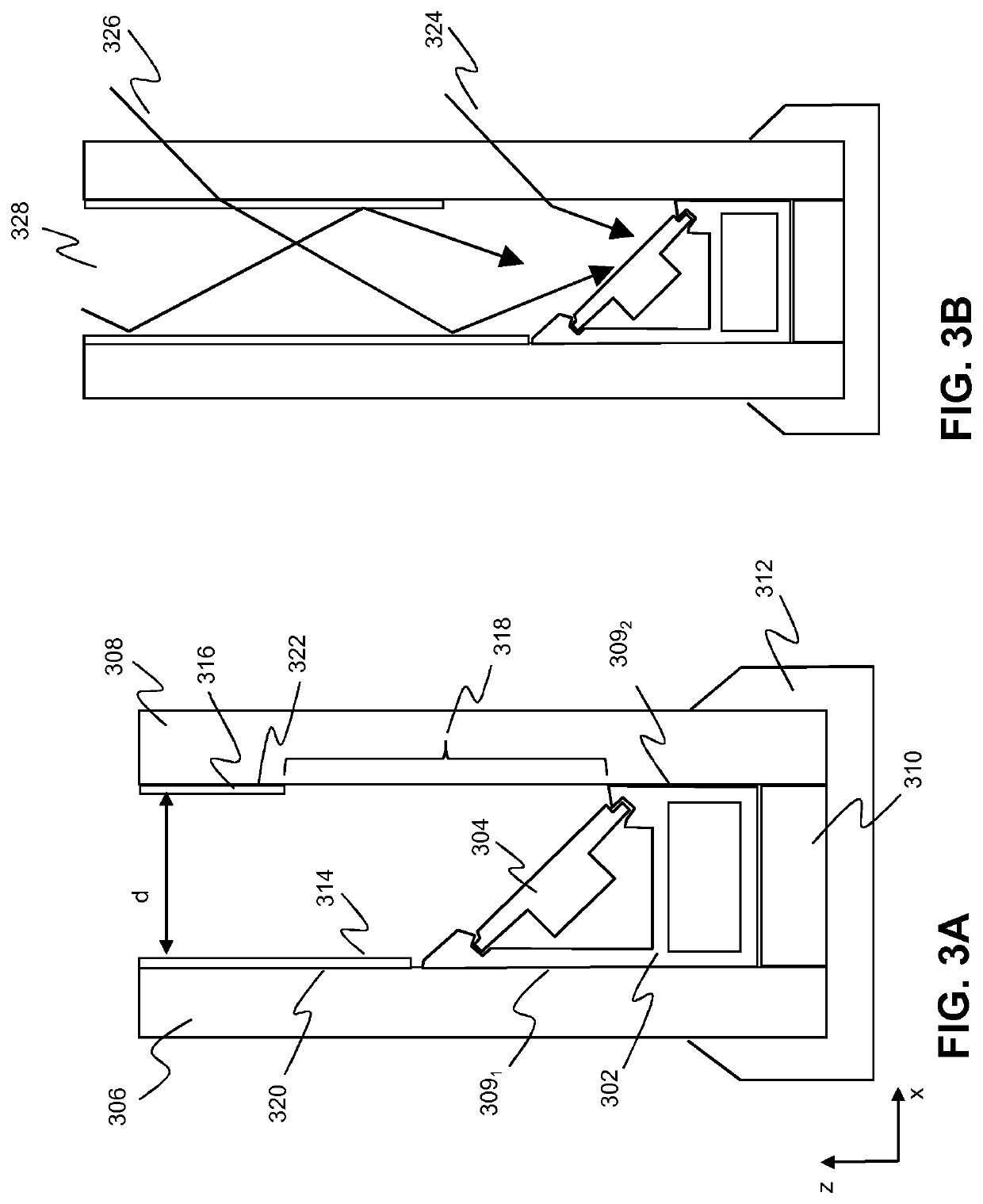
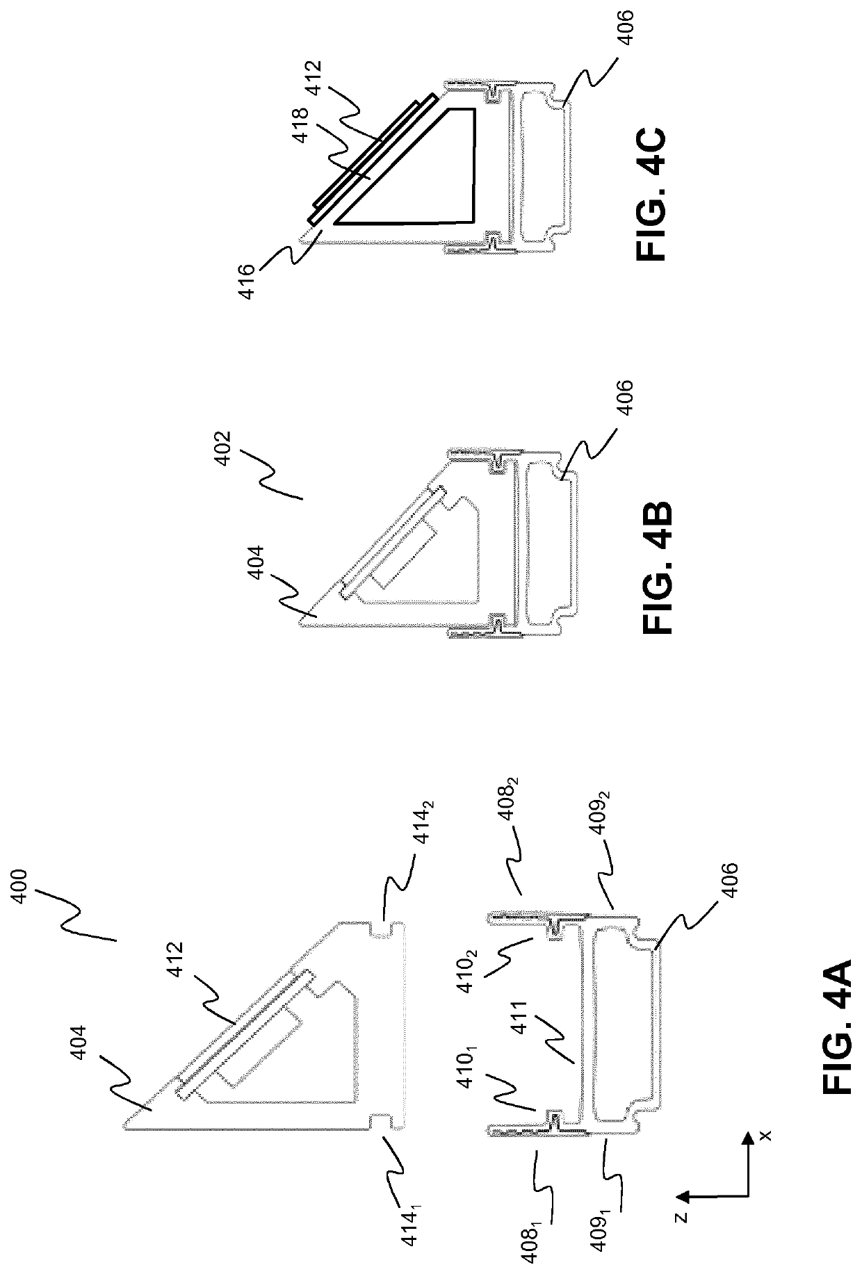
[0070]In this disclosure, improved power-generating glazing assemblies, in particular multi-pane glazing assemblies are described wherein PV cell modules are positioned and oriented within the cavity that is formed by two glass panes and a peripheral spacer structure, i.e. a spacer structure that is positioned in the peripheral area of the glass panes in order to keep the glass panes at a predetermined distance from each other. The PV cells are mounted onto the peripheral spacer structures such that the orientation of the light receiving surfaces of the PV cell modules are tilted towards the glass pane that functions as the outer glass pane. By mounting the PV cells directly on the peripheral spacer structure and orienting the PV cell modules in a tilted manner along the peripheral areas of the glass panes, the performance of the PV cells can be optimized without affecting the thermal properties of the glazing assembly. The glazing assemblies according to the invention thus include ...


PUM


Abstract

Glazing assembly are described comprising at least a first (inner) glass pane, a second (outer) glass pane and at least one peripheral spacer structure for providing a predetermined separation between the first and second glass pane, the peripheral spacer structure being positioned at the peripheral area of the first and second glass pane; one or more photovoltaic (PV) cell modules mounted on at least part of the peripheral spacer structure, the one or more PV cell modules being positioned in the space defined by the first and second glass panes and the peripheral spacer structure (inter-pane space); wherein at least part of the peripheral spacer structure comprises one or more mounting members adapted to orient a light receiving surface of PV cells of the PV cell modules in a tilted position with respect to the plane of the second (outer) glass pane.

Description

FIELD OF THE INVENTION[0001]The invention relates to glazing assemblies and spacer structures for such glazing assemblies, and, in particular, though not exclusively, to a power-generating multi-pane glazing assembly, a window comprising a power-generating glazing assembly, a modular power-generating spacer structure for a multi-pane glazing assembly and a corner connector and an electronic module for such power-generating spacer structure.BACKGROUND OF THE INVENTION[0002]Photovoltaics play an important role in transforming buildings into neutral, or net zero, energy consumers. Preferably such building locally produces as much energy as it consumes. Building-integrated photovoltaics (BIPV) are photovoltaic structures that are used to replace conventional building structures in parts of the building envelope such as the roof, skylights, windows or facades. BIPV structures are increasingly being incorporated into the construction as a principal or ancillary source of electrical power ...

Claims


Application Information

Patent Timeline
IPC IPC(8): H02S20/26H02S30/10H02S40/36H02J3/38E06B3/663E06B3/667E06B7/28
CPCE06B7/28E06B3/66342H02S30/10E06B3/66314H02S20/26H02S40/36H02J2300/26H02J3/381E06B3/667E06B3/6722E06B3/9641H01L31/0488E06B2003/66395H02S40/22Y02B10/10Y02E10/52Y02E10/56
Inventor ANDERS, SAMMY CHARLEY DAVEGRAPPERHAUS, FERDINAND LODEWIJK: STOCKHUIZEN, DRIM
Owner PHYSEE GRP BV
Learn More