Failure prediction device, failure prediction method, computer program, calculation model learning method, and calculation model generation method
a failure prediction and failure technology, applied in adaptive control, testing/monitoring control systems, instruments, etc., can solve the problems of inability to confirm the validity of the prediction, and the failure prediction of a plurality of individual components cannot be accurately predicted, so as to improve the accuracy of the prediction for each failure
- Summary
- Abstract
- Description
- Claims
- Application Information
AI Technical Summary
Benefits of technology
Problems solved by technology
Method used
Image
Examples
first embodiment
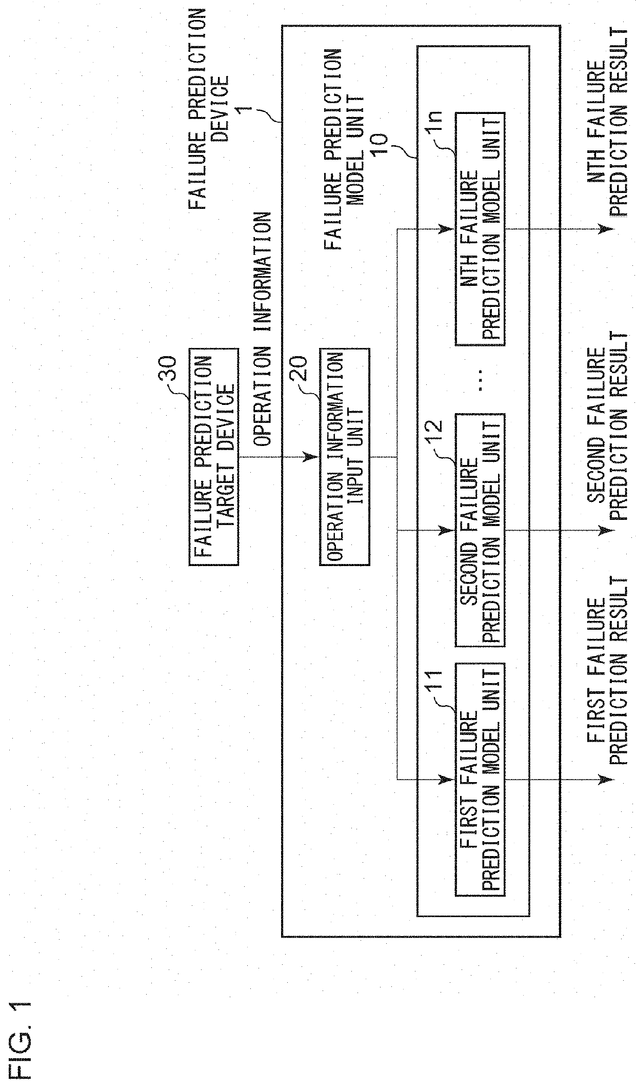
[0023]FIG. 1 is a functional block diagram showing the configuration of a failure prediction device 1 according to the first embodiment of the present invention. The failure prediction device 1 includes a failure prediction model unit 10 and an operation information input unit 20. The failure prediction model unit 10 has a plurality of failure prediction model units, that is, a first failure prediction model unit 11, a second failure prediction model unit 12, . . . , an nth failure prediction model unit 1n. Here, n is an integer of 2 or more. The first failure prediction model unit 11 predicts the first failure detail, the second failure prediction model unit 12 predicts the second failure detail, . . . , and the nth failure prediction model unit 1n predicts the nth failure detail. The operation information input unit 20 is connected to a failure prediction target device 30, which is a failure prediction target. The first failure detail, the second failure detail, . . . , and the nt...
second embodiment
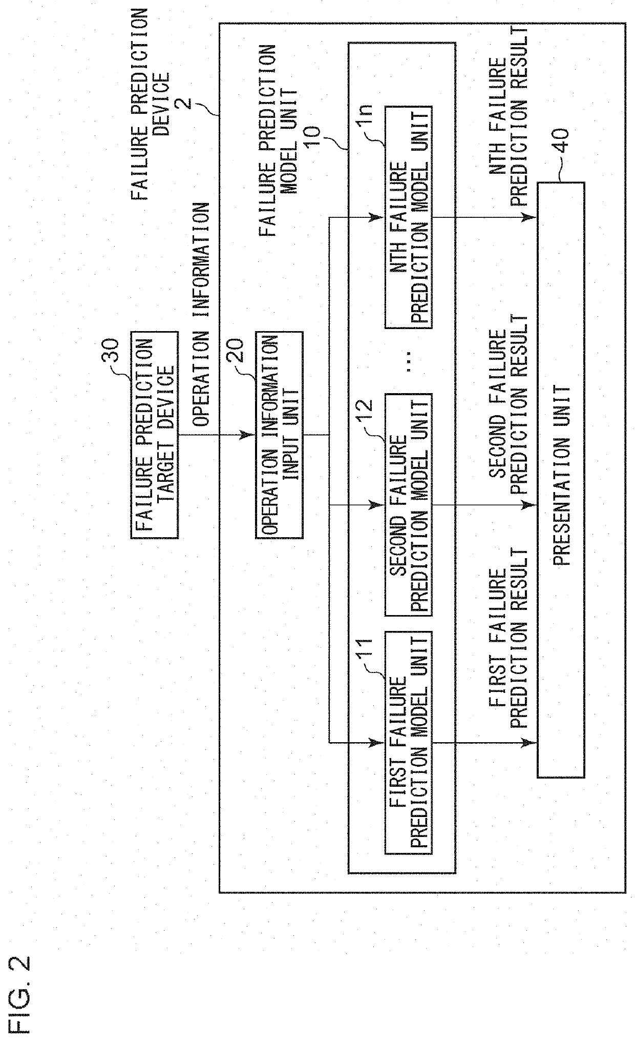
[0032]FIG. 2 is a functional block diagram showing the configuration of a failure prediction device 2 according to the second embodiment of the present invention. The failure prediction device 2 includes a presentation unit 40 in addition to the configuration of the failure prediction device 1 of FIG. 1
[0033]The presentation unit 40 presents differences between a calculation model corresponding to the most likely failure detail and calculation models corresponding to other failure details from among failure prediction results from the plurality of failure prediction model units, that is, the first failure prediction result, the second failure prediction result, . . . , and the nth failure prediction result.
[0034]Hereinafter, an example will be described in which the failure prediction model unit 10 has three failure prediction models: a first failure prediction model unit 11; a second failure prediction model unit 12; and a third failure prediction model unit 13. The first failure p...
third embodiment
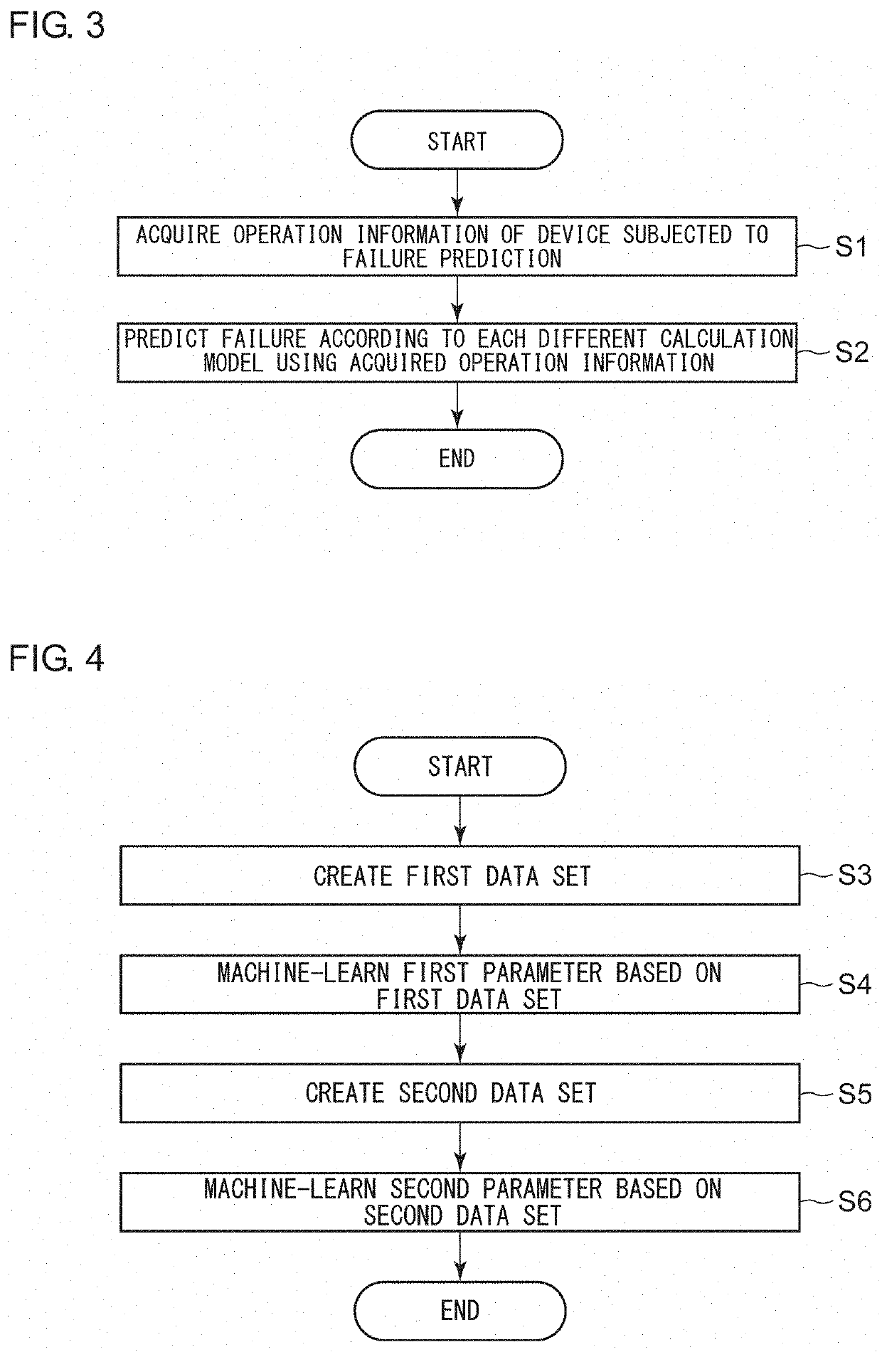
[0040]FIG. 3 is a flowchart of a failure prediction method according to the third embodiment of the present invention. The method includes an acquisition step S1 and a prediction step S2.
[0041]In the acquisition step S1, the present method includes acquiring operation information of a device subjected to failure prediction from the device.
[0042]In the prediction step S2, the present method includes inputting operation information acquired from the device subjected to failure prediction to each different calculation model generated based on a piece of operation information on operation up to the occurrence of a failure of a different detail among pieces of operation information of a predetermined device (calculation model generation device) so as to perform failure prediction. A calculation model generation method used here is the same as the one described in the first embodiment. Thus, a detailed description thereof will be omitted.
[0043]According to the present embodiment, since a ...
PUM
 Abstract
Description
Claims
Application Information
 - R&D
- Intellectual Property
- Life Sciences
- Materials
- Tech Scout
- Unparalleled Data Quality
- Higher Quality Content
- 60% Fewer Hallucinations
Browse by: Latest US Patents, China's latest patents, Technical Efficacy Thesaurus, Application Domain, Technology Topic, Popular Technical Reports.
© 2025 PatSnap. All rights reserved.Legal|Privacy policy|Modern Slavery Act Transparency Statement|Sitemap|About US| Contact US: help@patsnap.com


