Apparatus and method for high dynamic range counting by pixelated detectors

Active Publication Date: 2020-10-22
DIRECT ELECTRON LP
View PDF0 Cites 1 Cited by
  • Summary
  • Abstract
  • Description
  • Claims
  • Application Information

AI Technical Summary

Benefits of technology

[0010]The present disclosure relates to an apparatus and metho

Problems solved by technology

Typically, researchers are forced to compromise imaging across this spectrum by focusing on optimizing image quality for either high-flux or low-flux, but not both.
In general, this variability in d

Method used


Image

  • Apparatus and method for high dynamic range counting by pixelated detectors
  • Apparatus and method for high dynamic range counting by pixelated detectors
  • Apparatus and method for high dynamic range counting by pixelated detectors

Examples


Embodiment Construction

[0040]The terms “a” or “an”, as used herein, are defined as one or more than one. The term “plurality”, as used herein, is defined as two or more than two. The term “another”, as used herein, is defined as at least a second or more. The terms “including” and / or “having”, as used herein, are defined as comprising (i.e., open language). Reference throughout this document to “one embodiment”, “certain embodiments”, “an embodiment”, “an implementation”, “an example” or similar terms means that a particular feature, structure, or characteristic described in connection with the embodiment is included in at least one embodiment of the present disclosure. Thus, the appearances of such phrases or in various places throughout this specification are not necessarily all referring to the same embodiment. Furthermore, the particular features, structures, or characteristics may be combined in any suitable manner in one or more embodiments without limitation.

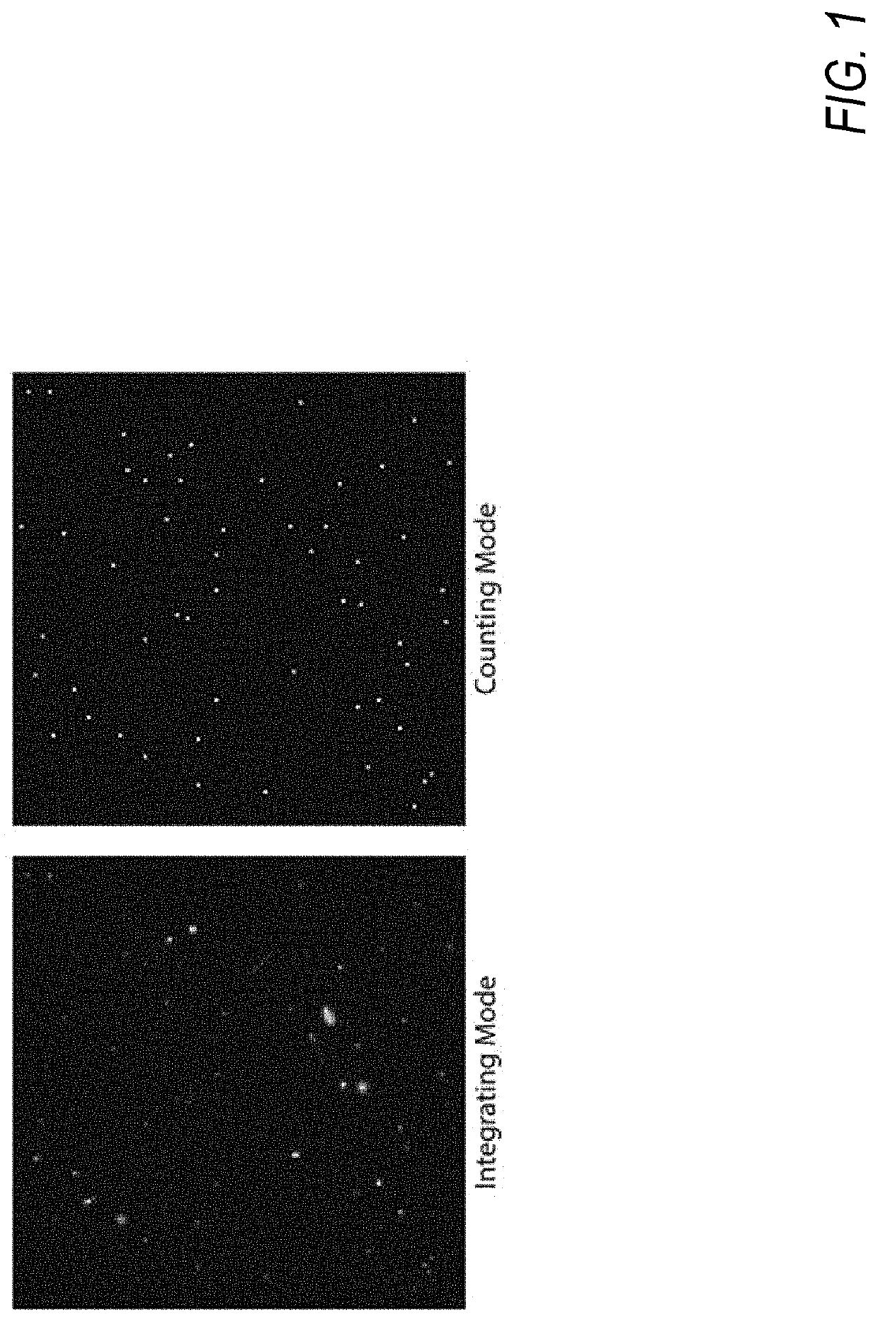
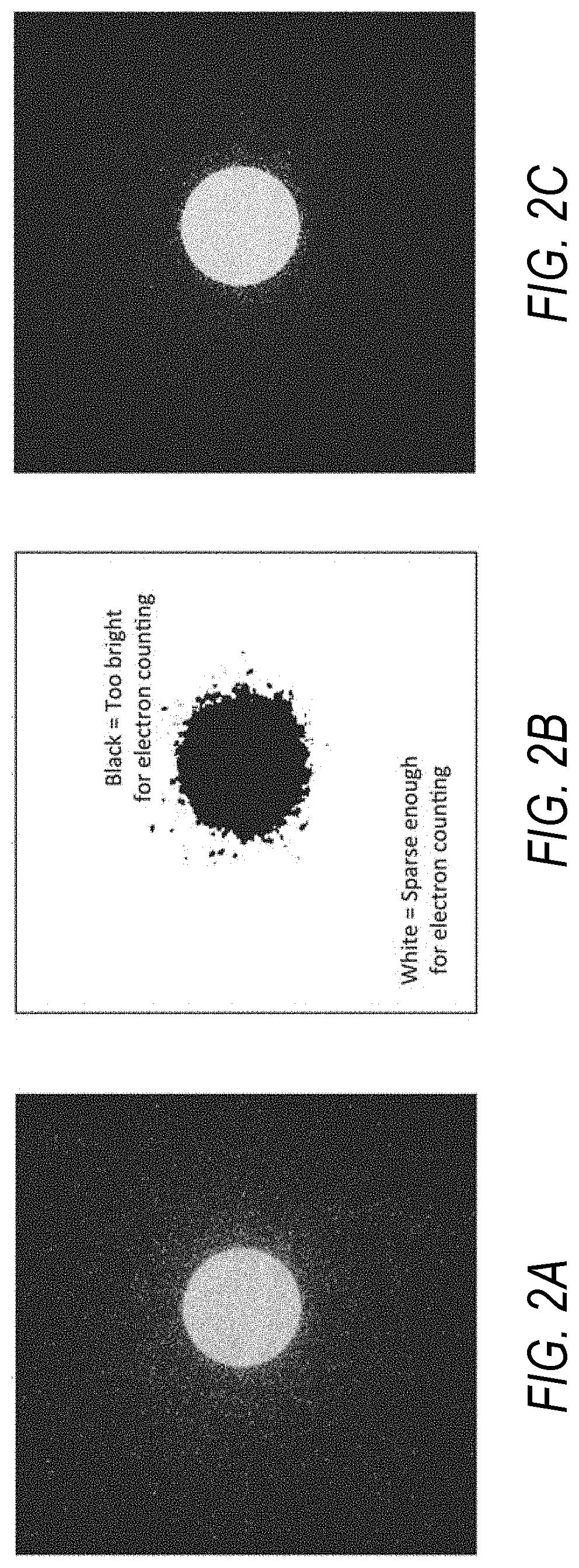
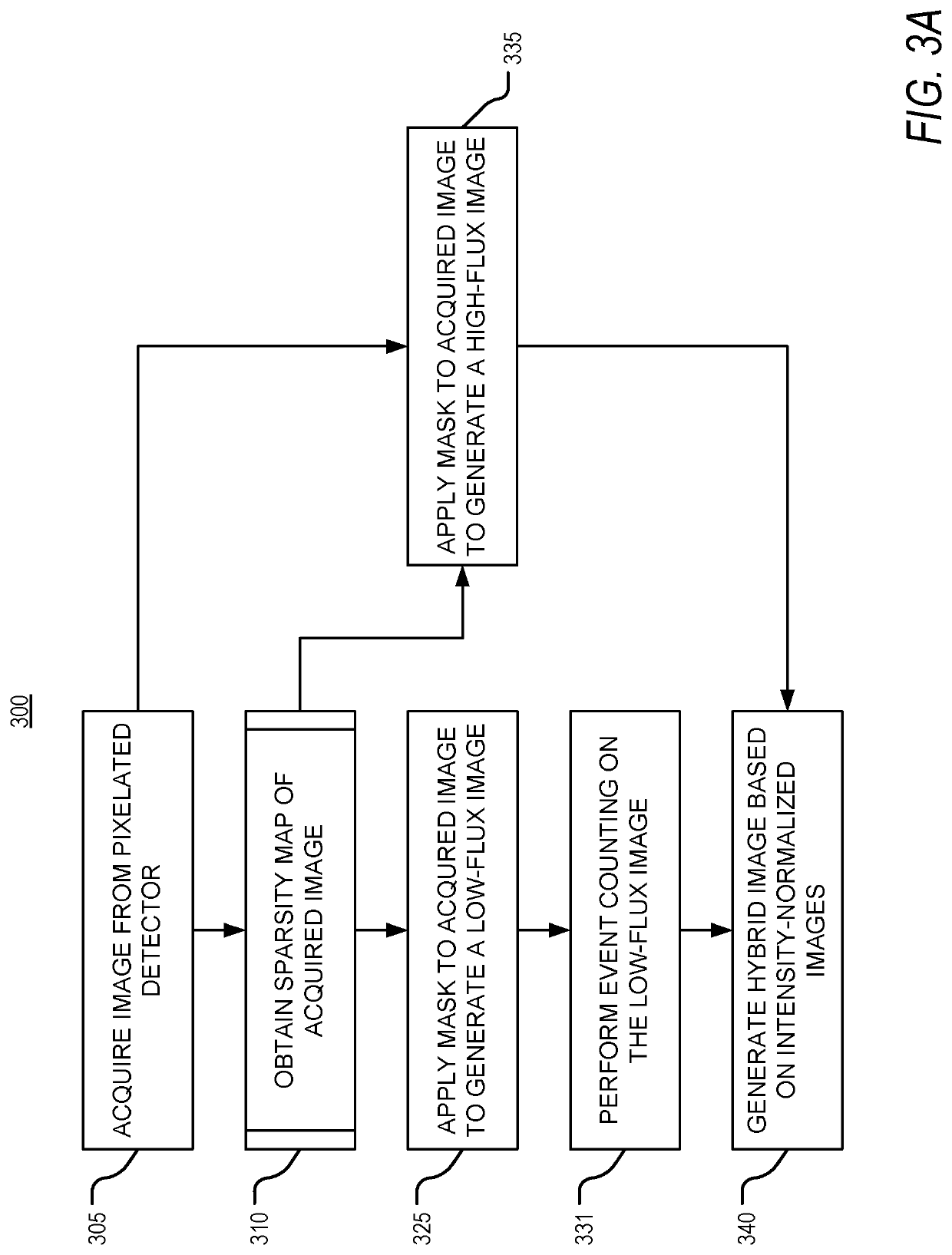
[0041]Different regions within a single ...


PUM


Abstract

The present disclosure relates to an apparatus and methods for generating a hybrid image by high-dynamic-range counting. In an embodiment, the apparatus includes a processing circuitry configured to acquire an image from a pixelated detector, obtain a sparsity map of the acquired image, the sparsity map indicating low-flux regions of the acquired image and high-flux regions of the acquired image, generate a low-flux image and a high-flux image based on the sparsity map, perform event analysis of the acquired image based on the low-flux image and the high-flux image, the event analysis including detecting, within the low-flux image, incident events by an event counting mode, multiply, by a normalization constant, resulting intensities of the high-flux image and the detected incident events of the low-flux image, and generate the hybrid image by merging the low-flux image and the high-flux image.

Description

CROSS-REFERENCE TO RELATED APPLICATIONS[0001]The present application claims priority to U.S. Provisional Application No. 62 / 836,555, filed Apr. 19, 2019, the teaching of which is incorporated by reference herein in its entirety for all purposes.STATEMENT REGARDING GOVERNMENT SUPPORT[0002]This invention was made with government support under Award Number DE-SC0018493 awarded by United States Department of Energy, Office of Science. The government has certain rights to the invention.STATEMENT REGARDING PRIOR DISCLOSURE BY THE INVENTORS[0003]Aspects of this technology are described in an article “4D STEM with a direct electron detector”, published in Microscopy and Analysis, on Jan. 30, 2020, which is incorporated herein by reference in its entirety.BACKGROUND FIELD OF THE DISCLOSURE[0004]The present disclosure relates to processing an image from a pixelated detector to maximize quality for both low intensity and high intensity regions in an image.DESCRIPTION OF THE RELATED ART[0005]Di...

Claims


Application Information

Patent Timeline
IPC IPC(8): H04N5/235H04N5/341H04N5/365
CPCH04N5/341H04N5/2355H04N5/3655G01N23/2251H01J37/244H01J37/28H01J2237/2441H01J2237/2446H01J2237/2802G01N2223/401G01N2223/418H01J2237/2614H04N23/81H04N23/667H04N23/741H04N25/445H04N25/531H01J2237/24592H01J2237/2806H01J2237/2817H04N5/00H04N25/40H04N25/673
Inventor BAMMES, BENJAMINBILHORN, ROBERT
Owner DIRECT ELECTRON LP
Why Eureka
Try Eureka