

Illuminator and display apparatus
- Summary
- Abstract
- Description
- Claims
- Application Information
AI Technical Summary
Benefits of technology
Problems solved by technology
Method used
Image

Examples
first embodiment
1. First Embodiment [1.0 Overview of Illuminator and Display Apparatus ]
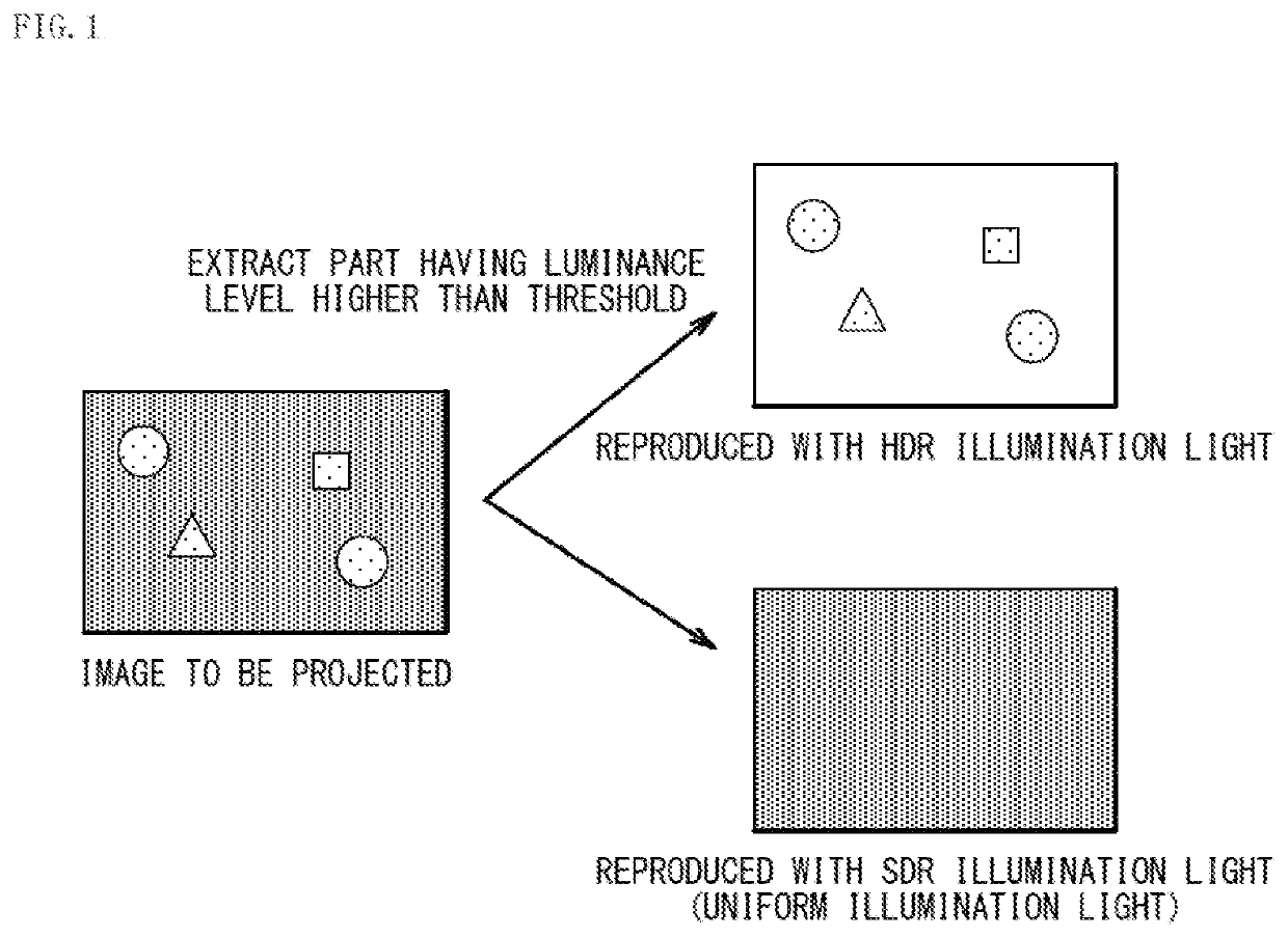
[0037]FIG. 1 schematically illustrates an overview of images generated by a display apparatus according to a first embodiment of the present disclosure.
[0038]The display apparatus according to the present embodiment is, for example, a projector. The display apparatus according to the present embodiment includes a light intensity modulator that performs intensity modulation on illumination light from an illuminator according to the present embodiment to generate an image (a projection image).
[0039]In the present embodiment, in order to provide a projector that achieves an image having high peak luminance and a high dynamic range, the illumination light is generated by an illumination optical system (the illuminator) utilizing a spatial optical phase modulator such as an SLM (Spatial Light Modulator) as a diffractor. In this case, as illustrated in FIG. 1, an image region having a luminance level higher than a pre...
first configuration example
[0072]FIG. 5 schematically illustrates a configuration of a main part of a projector 101A according to a first configuration example of the first embodiment.
[0073]The projector 101A according to the first configuration example describes a configuration example in a case where the diffractor 1 is a transmissive diffractor 1T (a transmissive optical phase modulator), and the light intensity modulator 51 is a DMD 52 (a reflective light intensity modulator). The transmissive diffractor 1T is, for example, a transmissive liquid crystal display device.
[0074]In the projector 101A according to the first configuration example, it is desirable that the light source 31 be a light source that emits coherent light with high coherence like a laser.
[0075]For example, if the transmissive diffractor 1T is a diffractor that performs phase modulation only on the P-polarized light, the S-polarized light of the entering light is transmitted as it is without undergoing phase modulation. This transmitted ...
second configuration example
[0077]FIG. 6 schematically illustrates a configuration of a main part of a projector 101B according to a second configuration example of the first embodiment.
[0078]The projector 101B according to the second configuration example includes a light source section 30A instead of the light source section 30 in the projector 101A according to the first configuration example illustrated in FIG. 5. The light source section 30A includes the light source 31, the PS converter 22, and the half-wave retarder 2.
[0079]In the projector 101B according to the second configuration example, the light source 31 is not limited to a light source that emits coherent light with high coherence like a laser. The light source 31 may be a light source such as an LED, a phosphor light source, or a lamp. In a case of using the LED, the phosphor light source, the lamp, or the like as the light source 31, as in the projector 101B according to the second configuration example, it is preferable to additionally insert...
PUM
 Abstract
Description
Claims
Application Information