Shape of slit opening and dimming device

A technology of dimming device and opening, applied in the direction of using optical devices, measuring devices, instruments, etc., can solve the problems of difficult control of movement, unstable relationship between gap position and lamp position, difficulty in automatic adjustment, etc., to reduce the volume Effect

Active Publication Date: 2011-11-30
V TECH CO LTD
View PDF2 Cites 0 Cited by
  • Summary
  • Abstract
  • Description
  • Claims
  • Application Information

AI Technical Summary

Problems solved by technology

[0024] In the conventional technology, automatic adjustment becomes difficult when the reflectance of the subject 1 is 400% or more due to the limit of reproducibility of the slit position
[0025] In addition, for the moving mechanism of the slit, even if the reproducibility of the slit position in the movement of the motor used in the moving mechanism is good, the positional relationship between the slit position and the lamp is not stable, and it is difficult to stably determine and control the slit position at 5 % on position
In addition, the larger the reflectivity, the smaller the adjustment range and the smaller the moving range of the moving mechanism, making it difficult to control the movement

Method used


Image

  • Shape of slit opening and dimming device
  • Shape of slit opening and dimming device
  • Shape of slit opening and dimming device

Examples


Embodiment Construction

[0046] use Figure 7 and Figure 8 The relationship between the shape of the opening of the slit and the light intensity of the lamp in one embodiment of the present invention will be described. Figure 7 It is a diagram for explaining the relationship between the maximum position of the slit and the amount of light emitted by the lamp in one embodiment of the present invention. also, Figure 8 It is a diagram for explaining the relationship between the minimum position of the slit and the amount of light emitted by the lamp in one embodiment of the present invention.

[0047] Figure 7 and Figure 8 The opening 91A of the slit in the slit adopts the following shape: when the slit is at the maximum slit position, the center of the part of the light-emitting part of the lamp that passes through the opening of the slit is on the axis of the lamp 90; The center of the portion of the light emitting portion that passes through the opening of the slit is at the periphery of the...


PUM


Abstract

Provided are a dimming method and a dimming device capable of automatically dimming even a subject with a high reflectance. In the dimming device that controls the amount of light to be illuminated so that the brightness level of the image becomes a predetermined value, the shape of the opening of the slit is used: at the maximum position of the slit, the center of the portion of the opening that passes through the slit in the light-emitting portion of the lamp On the axis of the lamp; at the minimum position of the gap, the center of the part of the light-emitting part of the lamp passing through the opening of the gap is on the periphery of the lamp (peripheral part of the light-emitting part of the lamp); In the device for adjusting the amount of light on the body, the amount of light passing through the slit changes exponentially according to the movement of the slit.

Description

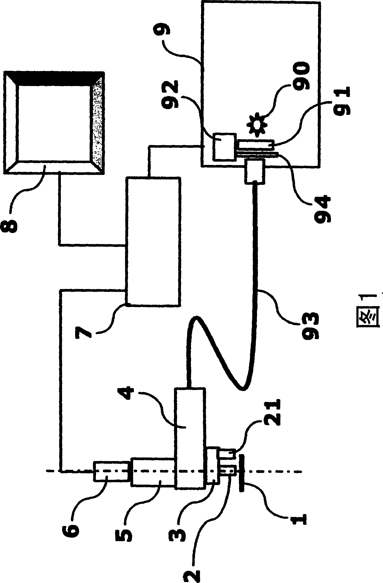
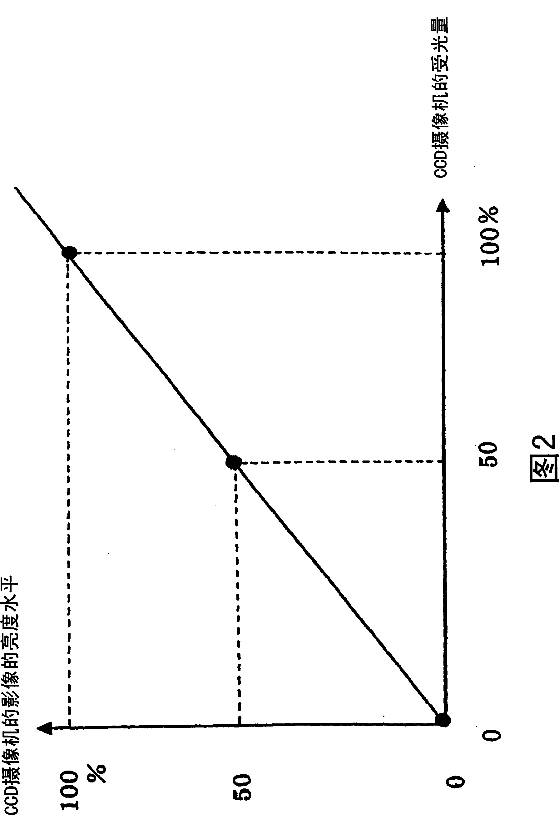
technical field [0001] The present invention relates to a light control device used in a device for non-contact inspection of minute objects such as substrates using an optical microscope and an image sensor. Background technique [0002] The dimming device is mainly used for non-contact inspection of IC (Integrated Circuit) wafers and LCD (Liquid Crystal Device) TFT (Thin Film Transistor) substrates and other image sensors using image sensors such as optical microscopes and CCD (Charge Coupled Device) cameras. used in processing systems. [0003] pass figure 1 and figure 2 , to describe the prior art. figure 1 It is a block diagram showing the configuration of a conventional image processing system using a microscope (for example, refer to Patent Document 1). figure 2 It is a graph showing the relationship between the amount of light received by the CCD camera 6 and the brightness level of the output image. 1 is the subject, 2 is the objective lens, 3 is the objectiv...

Claims


Application Information

Patent Timeline
Patent Type & Authority Patents(China)
IPC IPC(8): G01B11/00H04N7/18
Inventor 小菅正吾伊从洁野上大清水高博
Owner V TECH CO LTD
Why Eureka
Try Eureka