
Assembly of bending machine and support bench

Pending Publication Date: 2020-10-29
CML INTERNAT SPA
View PDF5 Cites 0 Cited by
  • Summary
  • Abstract
  • Description
  • Claims
  • Application Information

AI Technical Summary

Benefits of technology

The invention aims to simplify the structure of the bending machine and reduce the number of component parts.

Problems solved by technology

The structure described above is rather complex, because both the support arm and the two small arms which sustain it are connected to the bending unit, the first one in an oscillating manner, the second one in a partially rigid manner.

Method used


Image

  • Assembly of bending machine and support bench
  • Assembly of bending machine and support bench
  • Assembly of bending machine and support bench

Examples


Embodiment Construction

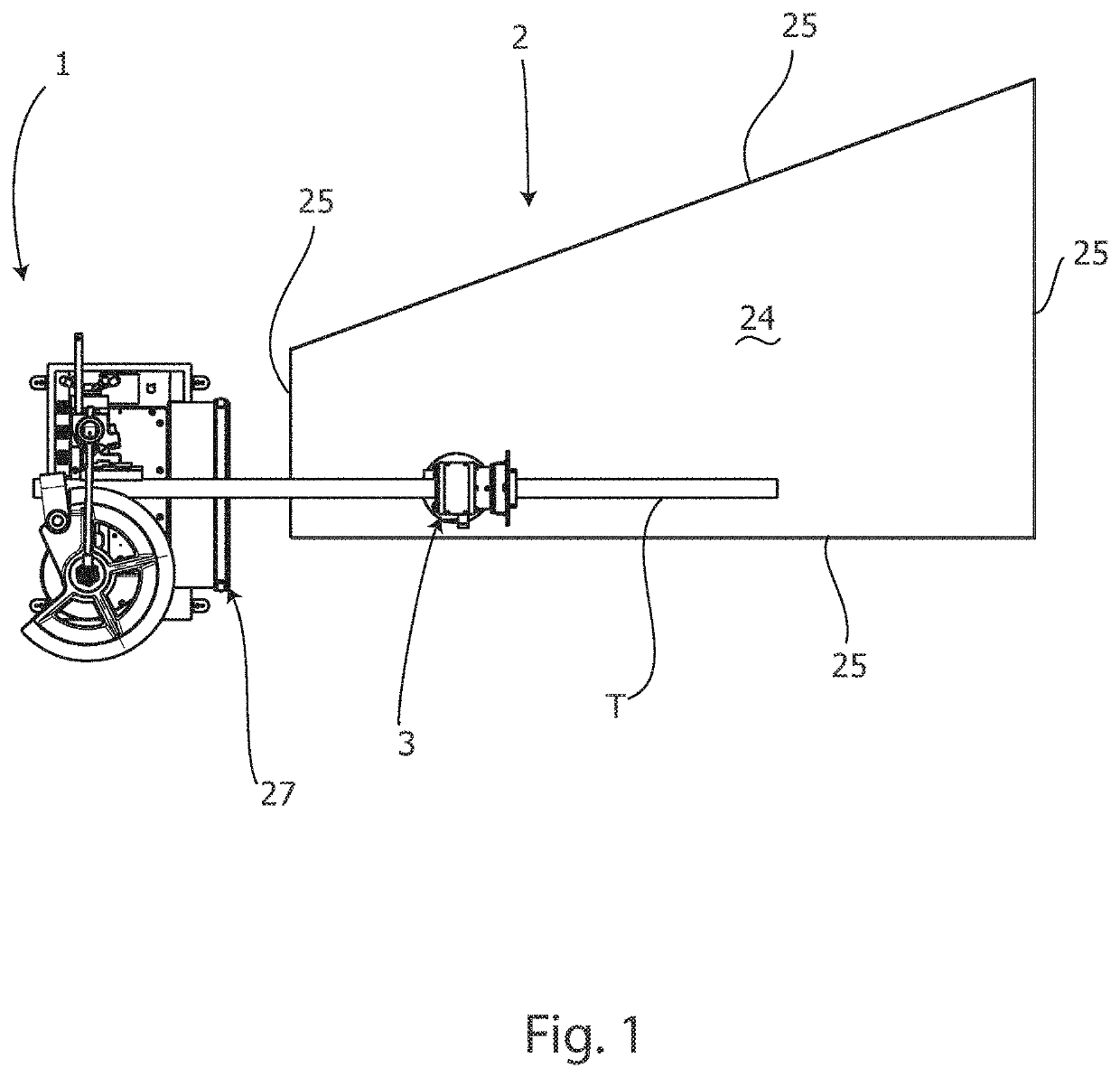
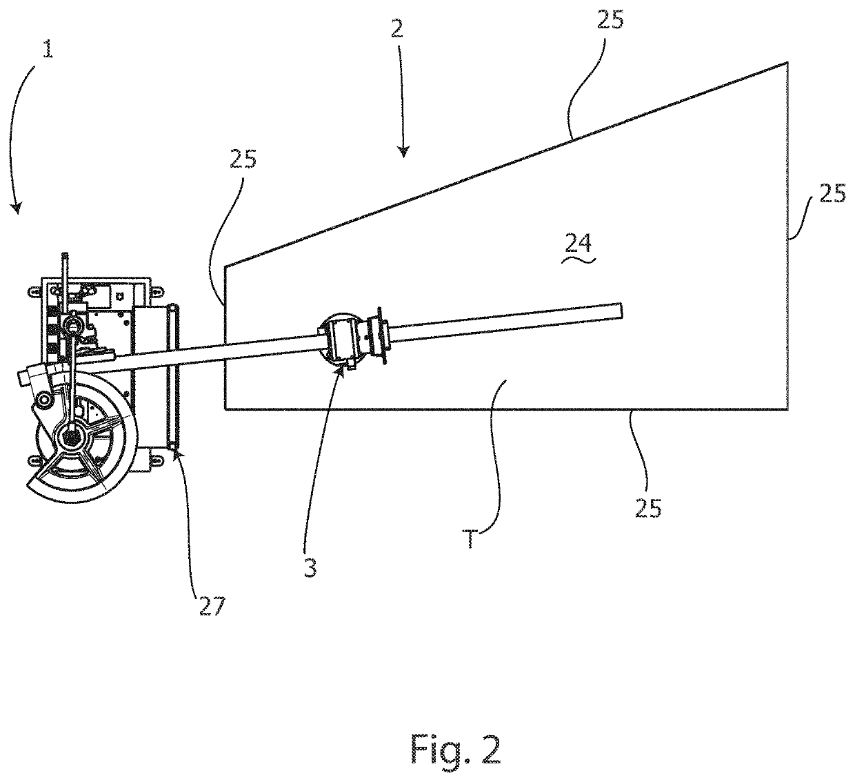
[0023]First of all, reference is made to FIGS. 1 and 2 which are top plan view, in a step preceding the bending and in a start step of bending, respectively, of an assembly of a fixed radius bending machine 1 and a support bench 2 for an elongated piece T to be bent according to a first embodiment of the invention. The elongated piece T to be bent is supported on the support bench 2 by means of a spindle 3. The spindle 3 is provided with at least one spherical support, shown below, so as to slide on the support bench 2, while the elongated piece T is bent. The bending machine 1 and the support bench 2 rest firmly on the ground. The bending machine 1 can be rigidly connected to the support bench 2, if necessary.

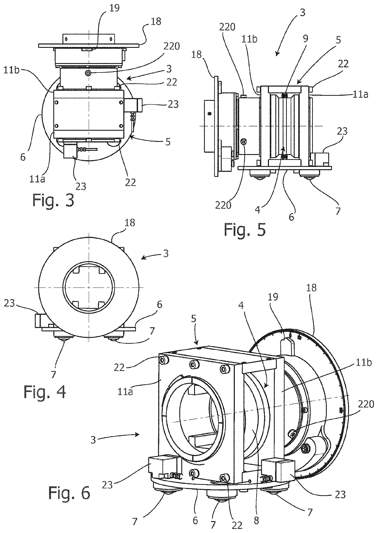
[0024]Reference is therefore made to FIGS. 3 to 7 which are a top plan view, a rear view, a side view, a perspective view and an exploded view of the spindle 3, respectively. The spindle 3 comprises a sleeve member 4 adapted to be connected to the elongated piece T to be bent,...


PUM

PropertyMeasurementUnit
Angleaaaaaaaaaa

Abstract

An assembly of a machine for bending an elongated piece (T) and relevant support bench is described. The elongated piece (T) is supported by a spindle (3) that comprises a sleeve member (4) suitable to be connected to the elongated piece (T) to be bent, and a spindle frame (5) which rotatably supports the sleeve member (4). The spindle frame (5) is mounted on a platform (6) provided at its bottom with at least a spherical support (7) so that the spindle (3) is able to slide freely on a support bench (2), while the elongated piece (T) is bent.

Description

FIELD OF THE INVENTION[0001]The present invention relates to an assembly of bending machine and support bench. As will be seen below, the bending machine can be of a constant or variable radius type.PRIOR ART[0002]EP0783927A1 discloses a bending machine comprising a bending unit and a support arm with a spindle for a pipe to be bent. The support arm is oscillating on the bending unit to follow the oscillation of the pipe, in particular in a starting step of bending. The support arm is sustained by two small arms pivoted together consecutively and resting on the ground. At its other end, a small arm is fixed to the bending unit, and the other small arm is pivoted in its free end to the support arm. The spindle is mounted slidable on the support arm by means of a linear guide.[0003]The structure described above is rather complex, because both the support arm and the two small arms which sustain it are connected to the bending unit, the first one in an oscillating manner, the second on...

Claims


Application Information

Patent Timeline
IPC IPC(8): B21D7/024B21D7/08
CPCB21D7/024B21D7/08B21D43/003B21D7/16B21D43/006
Inventor CAPORUSSO, ALESSANDROD'AGOSTINO, WERNER DAVIDE
Owner CML INTERNAT SPA
Features
  • Generate Ideas
  • Intellectual Property
  • Life Sciences
  • Materials
  • Tech Scout
  • Unparalleled Data Quality
  • Higher Quality Content
  • 60% Fewer Hallucinations
Learn More