
Apparatus for simultaneously applying torque to a plurality of jackbolts of a multi jackbolt tensioner

a multi-jackbolt tensioner and torque technology, applied in the direction of screw, load-modified fastener, wheel mounting apparatus, etc., can solve the problems of time-consuming and laborious tightening of each jackbolt, and be unsuitable for tightening large jackbolts, so as to reduce the angular separation

Active Publication Date: 2020-10-29
SUPERBOLT INC
View PDF4 Cites 3 Cited by
  • Summary
  • Abstract
  • Description
  • Claims
  • Application Information

AI Technical Summary

Benefits of technology

The present invention provides a tensioning apparatus for simultaneously tensioning multiple jackbolts of a multi-jackbolt tensioner. The apparatus includes a housing, one or more planetary gears, a ring gear, spindle gears, and a power transfer assembly. The apparatus allows for easy and efficient tensioning of multiple jackbolts with a single drive gear. The technical effects of the invention include improved tensioning efficiency, reduced labor costs, and improved safety.

Problems solved by technology

However, the use of MJTs has given rise to some other problems which need to be addressed.
Some industrial applications require implementation of multiple MJTs and in such applications, the tightening of each jackbolt can become time consuming.
However, it is believed that whilst the apparatus that is described in the '231 patent would be suitable for tightening small jackbolts it would not be suitable for tightening large jackbolts unless made so large that it would be difficult for an operator to carry.
Furthermore, it is believed that the '231 apparatus may be unable to provide sufficient torque to suitably tension larger jackbolts.

Method used


Image

  • Apparatus for simultaneously applying torque to a plurality of jackbolts of a multi jackbolt tensioner
  • Apparatus for simultaneously applying torque to a plurality of jackbolts of a multi jackbolt tensioner
  • Apparatus for simultaneously applying torque to a plurality of jackbolts of a multi jackbolt tensioner

Examples


Embodiment Construction

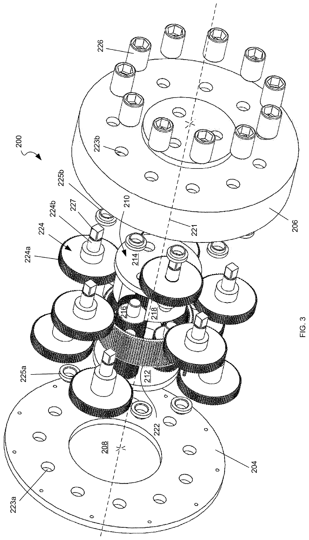
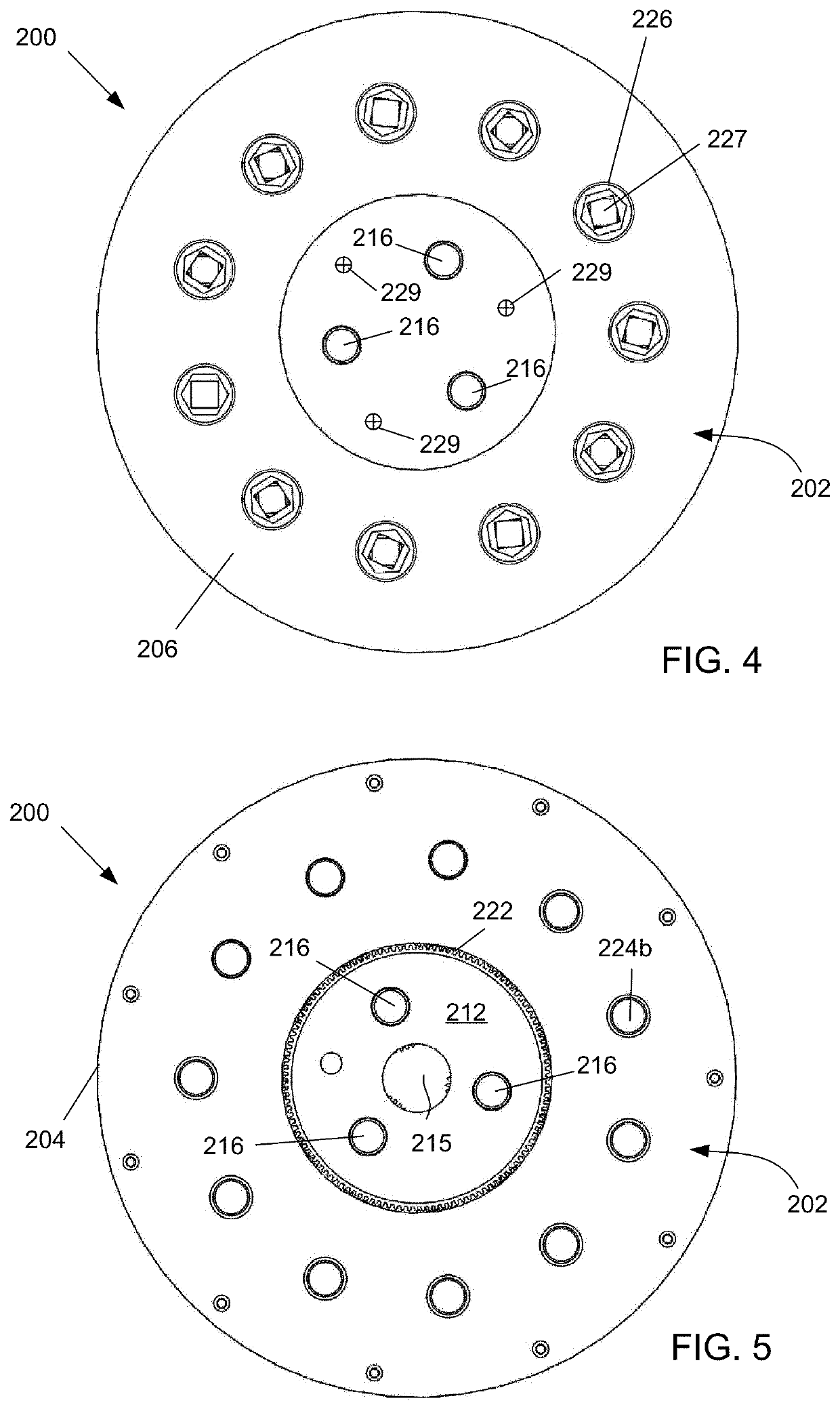
[0039]FIGS. 3 to 8 comprise various views of a tensioning apparatus 200 for simultaneously tensioning jackbolts of an MJT according to a preferred embodiment of the present invention.

[0040]The tensioning apparatus 200 includes a housing 202 that is comprised of a first portion being a back plate 204, and a second portion being a cover 206, which fasten together to define an internal space. The back plate 204 is formed as an annulus with a central circular hole 208. In the presently described embodiment the housing presents as squat cylinder with a longitudinal axis 221. It will be realised that in other embodiments the housing 202 may be of a different shape.

[0041]A planetary gear assembly (PGA) 210 is located coaxially within the housing 202. The planetary gear assembly comprises a bottom plate 212 and a top plate 214. Three planetary gears 216 are journaled between the bottom plate 212 and the top plate 214. The planetary gears are equiangularly disposed around the central axis 22...


PUM


Abstract

A tensioning apparatus is provided that is arranged to simultaneously tension a plurality of jackbolts of a multi jackbolt tensioner (MJT). The tensioning apparatus has a housing that is arranged for receiving a drive gear from a drive unit. The tensioning apparatus includes one or more planetary gears that are retained within the housing and which mesh with the drive gear in use. A ring gear encircles the one or more planetary gears and meshes with them. A plurality of spindle gears is retained in the housing. Each of the spindle gears has a spindle for coupling to a respective one of the jackbolts. The spindle gears are located around the ring gear and mesh with teeth on an outside of the ring gear. In use the drive gear rotates the one or more planetary gears to thereby rotate the spindle gears via the ring gear to thereby tension the jackbolts. The tensioning apparatus may be made compact by overlapping gear disks of the spindle gears and acts as a torque multiplier between the planetary gears and the spindle gears.

Description

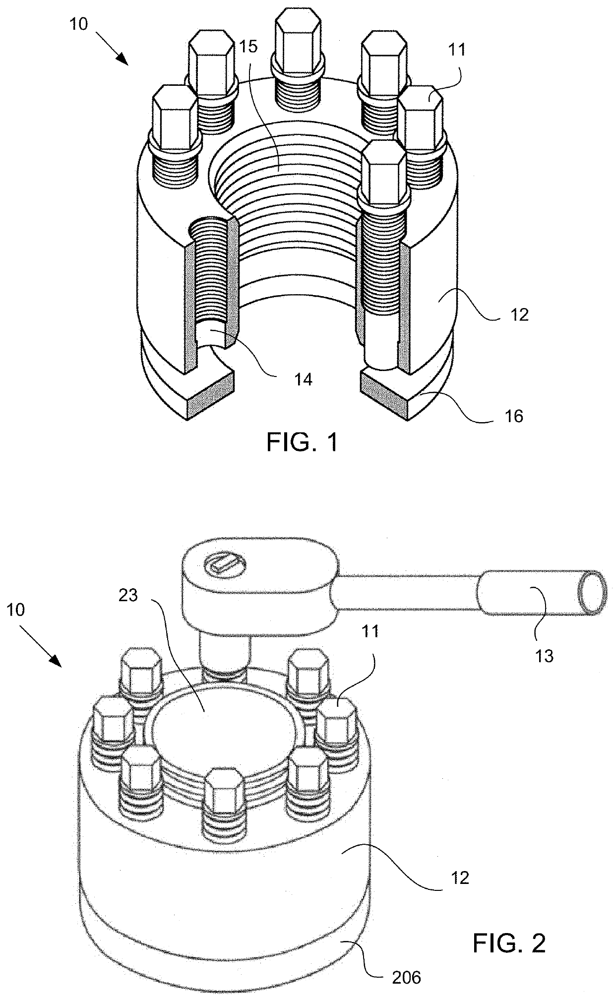
BACKGROUND[0001]A Multi-Jackbolt Tensioner (MJT), such as the tensioner sold under the Superbolt® brand, is generally used as a direct replacement for hex nuts, covered nuts, bolts, etc. of a size typically of 1″ or greater. A conventional (nut based) MJT threads onto an existing bolt or stud providing a highly effective means to “bolt up the joint”. The typical MJT consist of three components, i) a hardened washer to provide a hardened, flat surface for the jackbolts to “push” against; ii) an often round nut body that threads onto the existing bolt or stud and seats hand tight against the washer initially; and iii) a polar array of jackbolts that thread through the nut body so that their points force against the washer to pre-tension the bolt or stud.[0002]FIG. 1 is a partially cutaway version of an exemplary nut-style MJT 10. The MJT 10 comprises an annular body 12. The body 12 of the MJT 10 is formed with a threaded central hole 15 to receive a bolt, shaft, or stud. A polar array...

Claims


Application Information

Patent Timeline
IPC IPC(8): B25B21/00B23P19/06B25B17/00F16B31/04
CPCB25B21/002B25B17/00B23P19/069F16B31/04B23P19/067B60B29/006
Inventor MCPHEE, ANDREW DUNCAN
Owner SUPERBOLT INC
Learn More