

Method of controlling smart key
a smart key and key technology, applied in the field of smart keys, can solve the problems of limiting the vulnerability of conventional methods to hacking, and achieve the effect of preventing hacking and maximizing the efficiency of battery embedded devices
- Summary
- Abstract
- Description
- Claims
- Application Information
AI Technical Summary
Benefits of technology
Problems solved by technology
Method used
Image

Examples
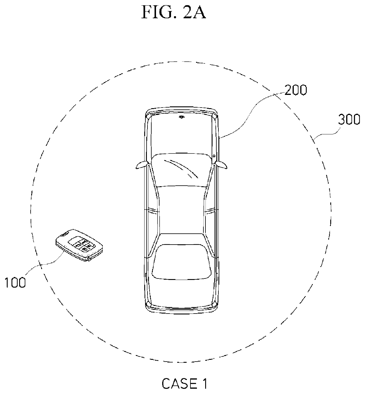
case 1
[0081]Thus, Case 1 is a case where a position of a smart key is within an LF reception distance, as illustrated in FIG. 2A.
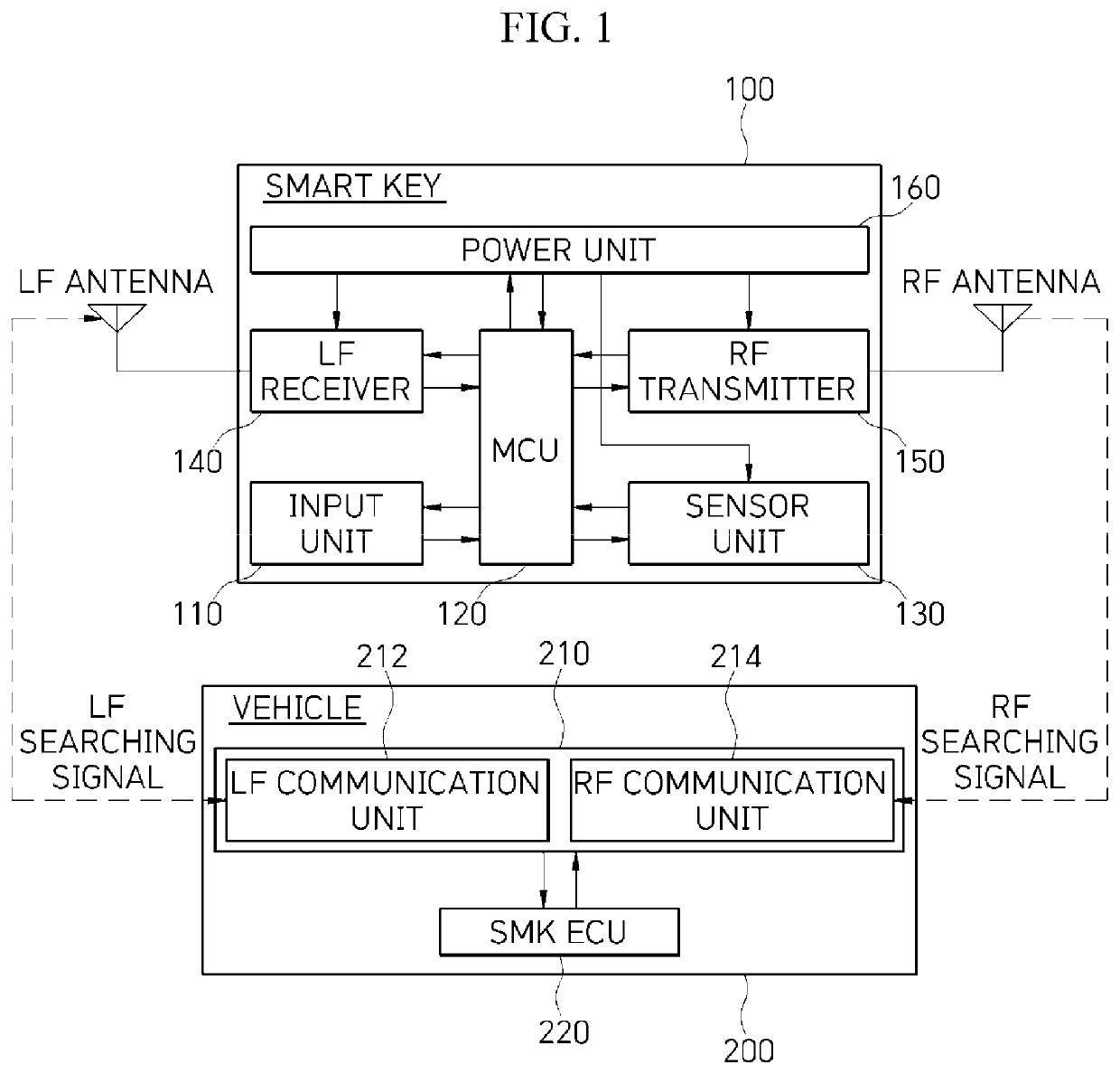
[0082]In Case 1, the sensor unit 130 may be turned off by a control command of the MCU 120, and the LF receiver 140 and the RF transmitter 150 may be turned on by the control command of the MCU 120. Case 1 may enable a PKE function or a vehicle start function. The following Table 1 illustrates operating states of the sensor unit 130, the LF receiver 140, and the RF transmitter 150 in Case 1.
TABLE 1Case 1Sensor unitLF receiverRF transmitterOperating stateOFFNormal ONNormal ON
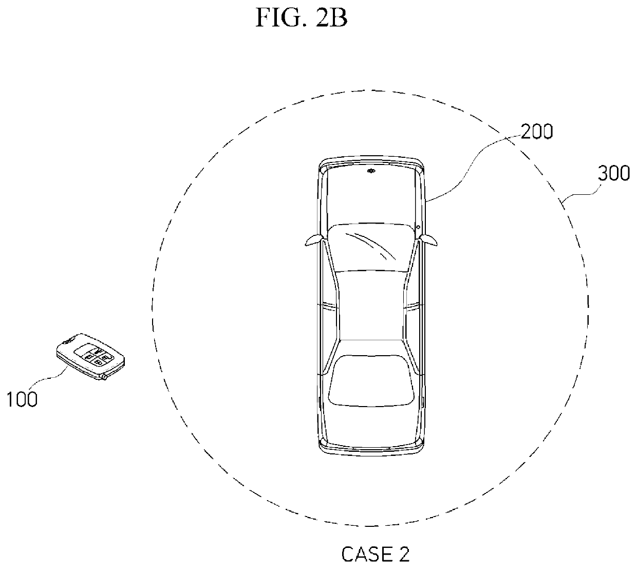
case 2 (a case where a position of a smart key is outside an lf reception distance , fig.1b)
[0083]Case 2 (a case where a position of a smart key is outside an LF reception distance, FIG. 1B)
[0084]In Case 2, the sensing strength (sensing sensitivity) of the sensor unit 130 may be adjusted based on a control command of the MCU 120, and the LF receiver 140 may be turned on by the control command of the MCU 120, for determination (determining that the smart key moves from the outside of the LF reception distance to the inside of the LF reception distance) of the following Case 4. In this case, in order to decrease battery consumption, the LF receiver 140 may be turned on only when the sensor unit 130 with adjusted sensing strength (sensing sensitivity) senses a motion of the smart key. One adjustment of the sensor unit 130 may be to increase the sensing strength.
[0085]Moreover, the RF transmitter 150 may be turned off by a control command of the MCU 120, and thus, RF transmission (automatic response) to LF reception may be blocked. In this case, the RF transmitter 150 may be t...
case 3 (a case distancing from a vehicle , fig.3a)
[0087]Case 3 (a case distancing from a vehicle, FIG. 3A)
PUM
 Abstract
Description
Claims
Application Information