
Boardwalk and Sidewalk System with Dual Use as Flood Control Barrier

a flood control barrier and boardwalk technology, applied in the field of boardwalks, to achieve the effect of convenient operation, low construction and installment cost, and widespread application

Active Publication Date: 2020-10-29
OMNITEK PARTNERS LLC
View PDF0 Cites 0 Cited by
  • Summary
  • Abstract
  • Description
  • Claims
  • Application Information

AI Technical Summary

Benefits of technology

The dual-purpose boardwalks provide effective flood protection without permanent obstructions, are cost-effective, and can be easily deployed and operated, offering a sustainable solution for frequent flooding events while maintaining functionality as pedestrian walkways.

Problems solved by technology

In addition, the design of such dual use boardwalks must be relatively simple, easy to operate, and be capable of being deployable manually since in situations such as during hurricanes or flooding there is no guarantee that there would be access to electrical power.

Method used


Image

  • Boardwalk and Sidewalk System with Dual Use as Flood Control Barrier
  • Boardwalk and Sidewalk System with Dual Use as Flood Control Barrier
  • Boardwalk and Sidewalk System with Dual Use as Flood Control Barrier

Examples


embodiment 30

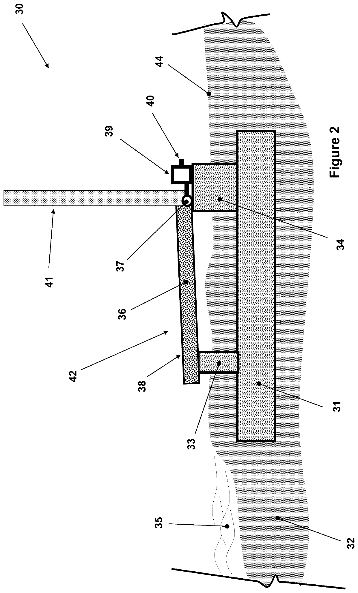
[0031]The embodiment 30 shown in FIG. 2 consists of a foundation base 31, which can be made out of reinforced concrete, which can be at least partially embedded in the beach (ground) area sand or soil 32, close or certain distance from the water 35 or potential flood area. The foundation based 31 may be a continuous slab if needed considering the type and characteristic of the soil / sand, but can also be made out of interconnected concrete structures that would provide the required “lifting” resistance to counter the forces of flood water, wave and wind gusts that the attached flood barrier could be subjected to during a storm as is later described. Over the foundation base 31 are provided with a series of at least two rows of support stands 33 and 34. At least the support stands 34, and possibly both support stands 33, 34, can also be made out of concrete with strong reinforcement and can be integrally formed with the structure and reinforcement elements of the foundation base 31. I...

embodiment 70

[0046]The embodiment 70 shown consists of certain pavement structure 72, over which the sidewalk planks 73 rests. In the sidewalk configuration 74, the planks 73 are shown with solid lines. In the configuration 74, the planks 73 serve as a sidewalk, with a relatively smooth surface 75, which can be walked upon or ridden upon by bicycles and the like, etc. In this configuration, the top surface 75 of the planks 36 can also be sloped slightly downward in the direction of allowing rain and washing water, etc., to flow towards the sidewalk drainage.

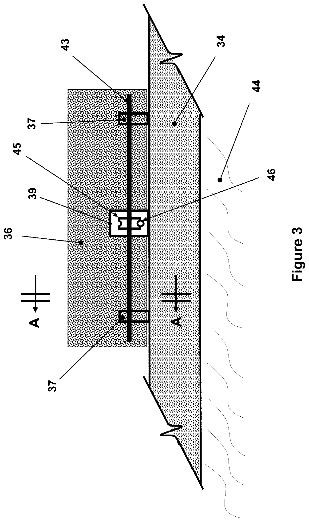
[0047]The sidewalk planks 73 can be attached to the foundation 76 of the building 71 via hinge joints 77 (similar to hinge joints 37 and the plank attached shaft 43 as shown in the schematic of FIG. 3). The supports of the hinge joints 77 can be rigidly attached to the concrete foundation 76 of the building 71 via reinforcing elements of the concrete foundation for increased load bearing. The hinge 77 shaft (not shown—but similar to 43 in FIG...


PUM


Abstract

A walkway for use between a shoreline of a body of water and at least a portion of a building exposed to the body of water, the walkway including: a base adjacent to the building; a plank having a surface for use by pedestrians to walk upon when the plank is in a first position at least indirectly disposed on the base, the plank having a first end rotatably connected to the base and having a second end extending from the first end away from the building along a length of the plank, the surface being exposed for use by the pedestrians to walk upon when the plank is in the first position; and a lifting mechanism operatively connected to the plank to rotate the plank from the first position to a second position where the length of the plank is oriented adjacent to a wall of the building to impede a rising height of the body of water.

Description

CROSS-REFERENCE TO RELATED APPLICATION[0001]This application is a continuation application of U.S. application Ser. No. 15 / 382,332, filed on Dec. 16, 2016, now U.S. Pat. No. 10,711,419 issued on Jul. 14, 2020, which claims the benefit of U.S. Provisional Application No. 62 / 268,469 filed on Dec. 16, 2015, the entire contents of each of which is incorporated herein by reference.BACKGROUND OF THE INVENTION1. Field of the Invention[0002]The present invention relates generally to boardwalks used as pedestrian walkway, service vehicles and the like along oceans, lakes and rivers and the like, which can be readily turned into protective walls for flood control.2. Prior Art[0003]Boardwalks are constructed close to shore in many areas to provide pedestrians a walkway overlooking beaches. The boardwalks are also sometimes used by relatively light service vehicles, food carts, and the like.[0004]Boardwalks are very popular with residents and visitors during good weather and particularly during...

Claims


Application Information

Patent Timeline
Patent Type & Authority Applications(United States)
IPC IPC(8): E02B3/10E02B3/06
CPCE02B3/102E02B3/06
Inventor RASTEGAR, JAHANGIR S.FARHADZADEH, ALI
Owner OMNITEK PARTNERS LLC
Learn More