Vehicle driving apparatus

Inactive Publication Date: 2020-10-29
TOYOTA JIDOSHA KK
View PDF0 Cites 0 Cited by
  • Summary
  • Abstract
  • Description
  • Claims
  • Application Information

AI Technical Summary

Benefits of technology

The vehicle driving apparatus described in this patent aims to prevent the transfer of heat from the differential limitation mechanism to the lubricant and minimize heat transfer to the electric motor. This is achieved through the arrangement of the electric motor and differential limitation mechanism on opposite sides of the speed reduction mechanism and differential mechanism in the width direction of the vehicle. The technical effects of this arrangement include the reduction of heat damage to the electric motor and differential limitation mechanism, improved performance and durability of the vehicle driving apparatus, and improved overall vehicle safety.

Problems solved by technology

Therefore, for example, the heat, which is generated by the electric motor when the electric motor is driven, is transmitted to the differential limitation mechanism, and a heat load applied to the differential limitation mechanism is increased.
When the heat load applied to the differential limitation mechanism is increased, a certain length of time is required to cool the differential limitation mechanism, thereby requiring some measures such as limitation on an operation time of the differential limitation mechanism and consequently resulting in problem of efficiency reduction.

Method used


Image

  • Vehicle driving apparatus
  • Vehicle driving apparatus
  • Vehicle driving apparatus

Examples


embodiment

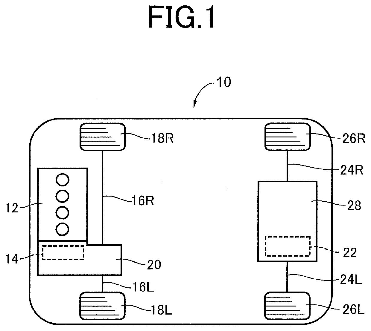
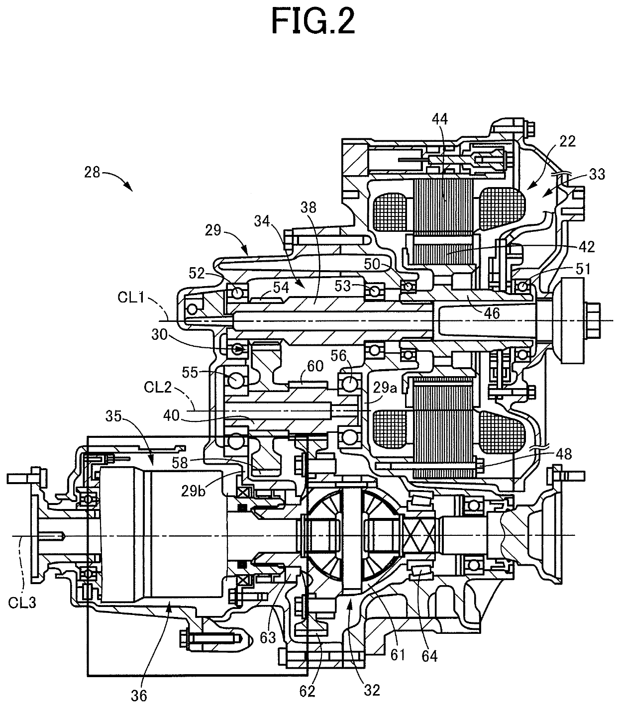
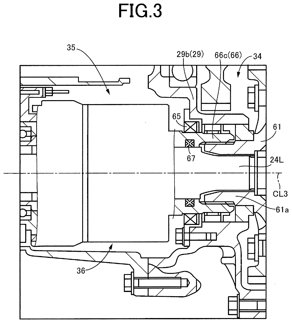
[0019]FIG. 1 is a view schematically showing a construction of a vehicle 10 to which the present invention is applied. As shown in FIG. 1, the vehicle 10 is an electric four-wheel drive vehicle that is provided with a front-wheel driving apparatus 20 and a rear-wheel driving apparatus 28. The front-wheel driving apparatus 20 stores therein an electric motor 14 and an engine 12 that is constituted by an internal combustion engine such as a gasoline engine or a diesel engine, which is configured to generate a drive force by combustion of a fuel, and is configured to transmit a drive force outputted by the electric motor 14 and / or a drive force outputted by the engine 12, to front right and left wheels 18R, 18L through respective front right and left axles 16R, 16L. The rear-wheel driving apparatus 28 stores therein an electric motor 22, and is configured to transmit a drive force outputted by the electric motor 22, to rear right and left wheels 26R, 26L through respective rear right a...


PUM


Abstract

A vehicle driving apparatus includes: an electric motor as a drive force source; a speed reduction mechanism configured to reduce a speed of rotation transmitted from the electric motor and output the rotation; a differential mechanism configured to distribute a drive force transmitted from the speed reduction mechanism, to a pair of drive shafts connected to respective right and left drive wheels; and a differential limitation mechanism including a friction clutch and configured to control an engaging torque of the friction clutch, for controlling a differential limiting torque by which a differential effect provided by the differential mechanism is to be limited. The electric motor and the differential limitation mechanism are disposed on respective opposite sides of the speed reduction mechanism, and are disposed on respective opposite sides of the differential mechanism.

Description

This application claims priority from Japanese Patent Application No. 2019-082351 filed on Apr. 23, 2019, the disclosure of which is herein incorporated by reference in its entirety.FIELD OF THE INVENTION[0001]The present invention relates to a vehicle driving apparatus configured to output a drive force of an electric motor as a drive force source, to right and left drive wheels through a differential mechanism.BACKGROUND OF THE INVENTION[0002]There is proposed a vehicle driving apparatus that includes: an electric motor as a drive force source; a speed reduction mechanism configured to boost the drive force of the electric motor and to output the drive force; a differential mechanism configured to distribute the drive force outputted from the speed reduction mechanism, to a pair of drive shafts connected to respective right and left drive wheels; and a differential limitation mechanism including a friction clutch, and configured to control an engaging torque of the friction clutch...

Claims


Application Information

Patent Timeline
IPC IPC(8): F16H48/22
CPCF16H48/22F16H2048/364F16H2048/366B60K17/16F16H37/08F16H57/029F16H57/04F16H57/0413F16H2057/02034F16H2057/02043B60K1/00B60K17/165B60K2001/001
Inventor MICHISHITA, MASAYA
Owner TOYOTA JIDOSHA KK
Why Eureka
Try Eureka