Method and Apparatus for Treating Malocclusions and Teeth Alignment

a technology for malocclusions and teeth, applied in the field of methods and apparatus for treating malocclusions and teeth alignment, can solve the problems of anterior teeth having a tendency to adversely flare or tip forward, undesirable herbicide devices, and discomfort near the front of the mouth

Pending Publication Date: 2020-11-05
DISCHINGER TERRY G +2
View PDF2 Cites 3 Cited by
  • Summary
  • Abstract
  • Description
  • Claims
  • Application Information

AI Technical Summary

Benefits of technology

[0014]A further aspect of the present invention relates to an orthodontic appliance, and wherein the multiple section, elongated, telescoping assembly further comprises an outer, cylindrically shaped tube having opposite first and second ends, inwardly and outwardly facing surfaces, and a longitudinal axis which extends between the opposite first and second ends, and wherein the inwardly facing surface of the outer, cylindrically shaped tube defines an internal cavity which extends between the first and second ends thereof; a first attachment member made integral with the outside facing surface of the outer, cylindrically shaped tube, and which has a distal second end which is positioned laterally outwardly relative to the cylindrically shaped tube, and wherein an aperture is formed in the distal end of the first attachment member, and is sized so as to allow the distal end of the first portion of one of the fasteners to pass therethrough, and wherein the first attachment member is oriented within the gap that is defined between the second portion of one of the fasteners, and the main body of the respective archwire couplers, and where the first attachment member rotates freely about the gap; a first, intermediate tube which is defined by an elongated main body, and which further has opposite first and second ends, and an outside and inside facing surface; and wherein the inside facing surface of the first intermediate tube defines an internal cavity extending between the first and second ends thereof, and wherein the first intermediate tube is telescopingly received within the internal cavity which is defined by the outer, cylindrically shaped tube, and is further reciprocally moveable relative thereto; a second, intermediate tube which is defined by an elongated main body, and which further has opposite first and second ends, and an outside, and inside facing surface; and wherein the inside facing surface of the second intermediate tube defines an internal cavity extending between the first and second ends thereof, and wherein the second, intermediate tube is telescopingly received within the internal cavity of the first, intermediate tube, and is reciprocally moveable relative thereto; an inner, elongated rod having a main body, and which further has opposite first and second ends, and an outside facing surface, and wherein the inner elongated rod is telescopingly received within the internal cavity of the second, intermediate tube, and is further reciprocally moveable relative thereto; and a second attachment member which is made integral with the second end of the inner elongated rod and which further defines an aperture which is sized so as to allow the distal end of the first portion of another one of the fasteners to pass therethrough, and wherein the first attachment member is received in the gap that is defined between the second portion of the fastener, and the main body of the respective archwire couplers, and rotates freely about the gap, and wherein the first and second attachment members are individually affixed to one of the pair of archwires by way of the respective archwire couplers, and individual cooperating fasteners.
[0027]An even still further aspect of the present invention relates to an orthodontic appliance, and wherein the second attachment member is defined by a main body, and which has a proximal end which further is made integral with the second end of the inner elongated rod; and a second, distal end which is located longitudinally outwardly relative to the inner elongated rod, and along the longitudinal axis which is defined by the outer, cylindrically shaped tube, and wherein the aperture defined by the second attachment member is formed in the distal end of the second attachment member, and is further sized so as to allow a portion of one of the fasteners to pass therethrough, and then cooperate with the archwire coupler which is located on the archwire and which is further placed on the lower dental arch of the patient, and wherein the second attachment member rotates freely about the fastener.
[0030]A still further aspect of the present invention provides that the individual archwire couplers on the same archwire are at least partially controllably axially slidably movable along the respective archwire between an adjacent mesial orthodontic bracket and an adjacent distal orthodontic bracket; and cooperation of a generally rectilinear cross-sectional configuration of the respective archwire, and a generally rectilinear peripheral configuration of the archwire receiving region defined by the archwire coupler and a distal end of fastener prevents axial rotation of the archwire coupler relative to the archwire; and the distal end of the fastener maintains the respective archwire in the generally rectilinear archwire receiving region defined in the archwire coupler.

Problems solved by technology

Herbst devices have been undesirable from a patient's standpoint because they are typically designed to have long and stiff assemblies, and are further positioned in the mouth such that these devices can typically be easily viewed by others during a patient's treatment.
Additionally, these same devices often create discomfort near the front of the mouth.
In addition to the earlier mentioned shortcomings, anterior teeth have a tendency to adversely flare or tip forward when they are connected to a Herbst device.
While conventional Herbst devices may sometimes be used to correct a malocclusion at the same time that archwires and brackets are used, so as to prevent the aforementioned tipping, there are significant challenges in doing so.
More specifically, when the Herbst device extends from a molar on the upper dental arch to a bicuspid tooth on the lower dental arch, the device and tube assembly of the Herbst assembly may obstruct access to a large number of teeth.
This resulting obstruction makes it extremely difficult for practitioners to properly affix conventional orthodontic brackets to the anterior facing surfaces of teeth requiring treatment.
Various ad hoc approaches by various practitioners have been attempted to address this problem, however, none of them have provided a suitable solution.
Further, it has often become necessary, after using a Herbst device to correct or straighten teeth that have been affected by the use of the Herbst device.
This, of course, increases the overall treatment time and cost borne by the patient.
However, these devices have not always been successful in both correcting the Class II malocclusion, and simultaneously allowing teeth to be straightened during the same treatment interval.
Often it has been found that the malocclusion correction is completely satisfactory, but the movement of the teeth has not been completed.
Therefore, unwanted additional orthodontic correction and thus additional time and expense must be undertaken to achieve the clinically desired result.

Method used


Image

  • Method and Apparatus for Treating Malocclusions and Teeth Alignment
  • Method and Apparatus for Treating Malocclusions and Teeth Alignment
  • Method and Apparatus for Treating Malocclusions and Teeth Alignment

Examples


Embodiment Construction

[0052]This disclosure of the invention is submitted in furtherance of the constitutional purposes of the U.S. Patent Laws “to promote the progress of science and useful arts” (Article 1, Section 8).

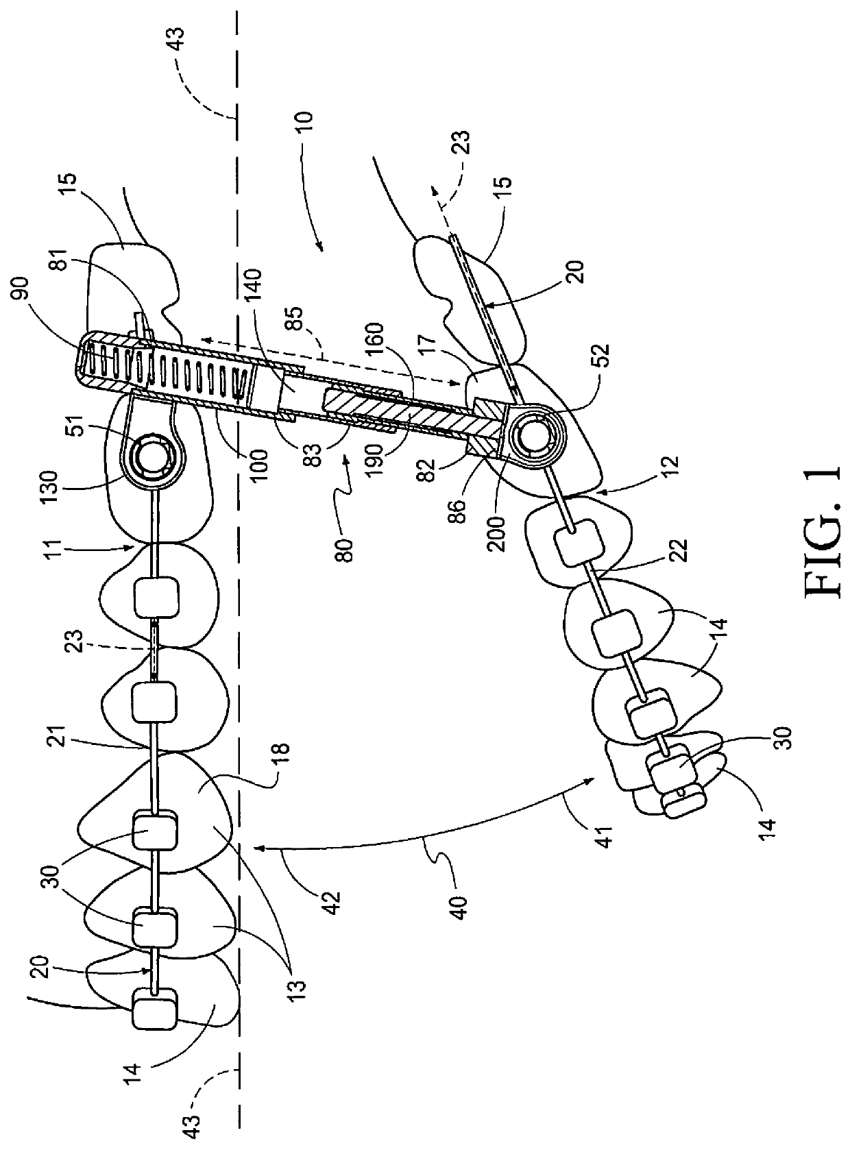
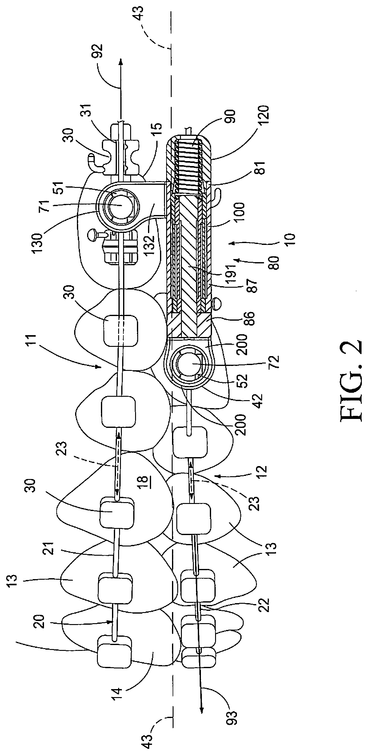
[0053]Turning now to the drawings which are referenced, above, the apparatus of the present invention is generally indicated by the numeral 10 in FIG. 1, and following. The invention comprises an orthodontic appliance 10 which cooperates with both the upper and lower dental arches, and which are generally indicated by the numerals 11, and 12, of a patient so as to achieve the objectives of a predetermined orthodontic treatment regimen. The upper and lower dental arches 11 and 12 are formed of a multiplicity of teeth 13, some of which may be malpositioned, one relative to the others, and which are further variously located within the upper and lower dental arches. The upper and lower dental arches 11 and 12 have a forward portion or mesial region 14, and an opposite rearward portion or dis...


PUM


Abstract

An orthodontic appliance is disclosed and which cooperates with both the upper and lower dental arches of a patient and which includes an archwire coupler which is attached to individual archwires that are releasably attached to individual orthodontic brackets on the anterior facing surface of a patient's teeth requiring orthodontic treatment; and a multiple section elongated telescoping assembly which is rotatably and releasably coupled to the archwires attached to the upper and lower dental arches of a patient undergoing treatment, and wherein the multiple section elongated telescoping assembly effects movement of the upper dental arch in a rearward direction, and the lower dental arch in a forward direction when the multiple section elongated telescoping assembly is in a given position along a predetermined course of travel.

Description

RELATED PATENT APPLICATIONS[0001]This utility patent application is a Continuation in Part (CIP) patent application of earlier filed (and currently pending) U.S. Non-Provisional patent application Ser. No. 15 / 410,350 filed on 19 Jan. 2017 and titled METHOD AND APPARATUS FOR TREATMENT OF MALOCCLUSIONS AND TEETH ALIGNMENT, for which a Notice of Allowance has been received, but has not issued; and said U.S. Ser. No. 15 / 410,350 is a Continuation in Part (CIP) patent application of earlier filed U.S. Non-Provisional patent application Ser. No. 14 / 552,352 (now abandoned), filed on 24 Nov. 2014 and titled METHOD AND APPARATUS FOR TREATMENT OF MALOCCLUSIONS AND TEETH ALIGNMENT; and said U.S. Ser. No. 14 / 552,352 is a Continuation in Part (CIP) patent application of still earlier filed U.S. Non-Provisional patent application Ser. No. 14 / 209,685 (now abandoned), filed on 13 Mar. 2014 and titled METHOD AND APPARATUS FOR TREATMENT OF MALOCCLUSIONS AND TEETH ALIGNMENT. This US Non-Provisional pat...

Claims


Application Information

Patent Timeline
Patent Type & Authority Applications(United States)
IPC IPC(8): A61C7/36
CPCA61C7/14A61C7/20A61C7/36A61C7/28
Inventor DISCHINGER, TERRY G.DISCHINGER, WILLIAM M.LUSE, STEVEN O.
Owner DISCHINGER TERRY G
Why Eureka
Try Eureka