Surgical smoke removing device

a smoke removal and surgical technology, applied in the field of air pollution reduction devices, can solve the problems of air pollution, polluted air, air pollution, etc., and achieve the effect of reducing air pollution concentration

Pending Publication Date: 2020-11-05
NAT CHENG KUNG UNIV
View PDF10 Cites 2 Cited by
  • Summary
  • Abstract
  • Description
  • Claims
  • Application Information

AI Technical Summary

Benefits of technology

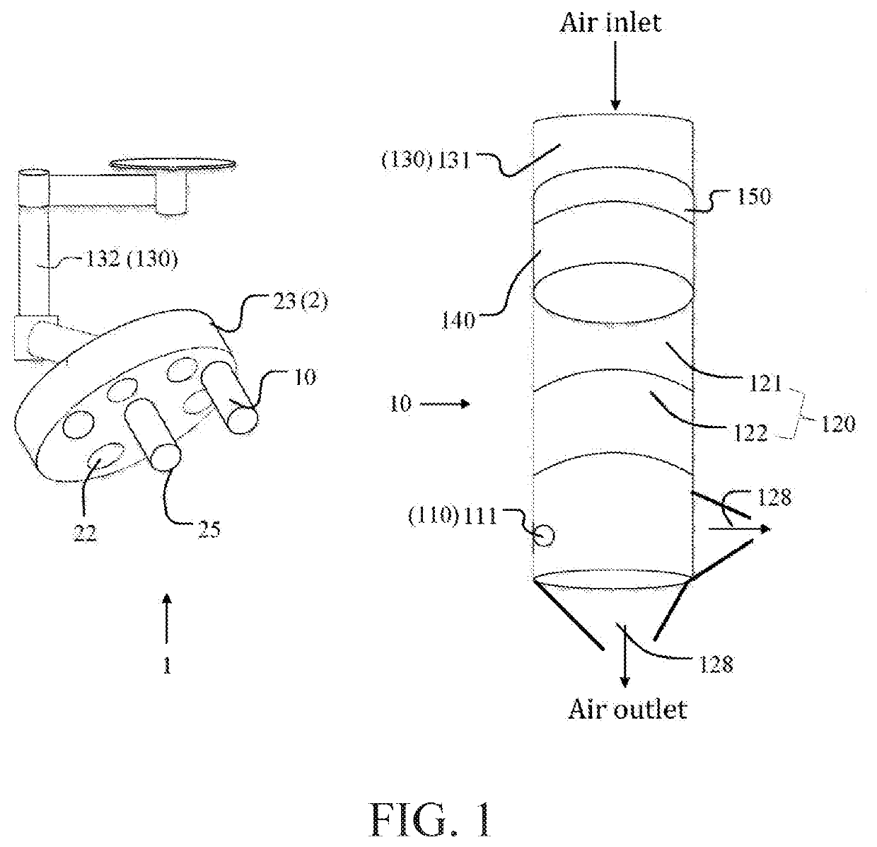
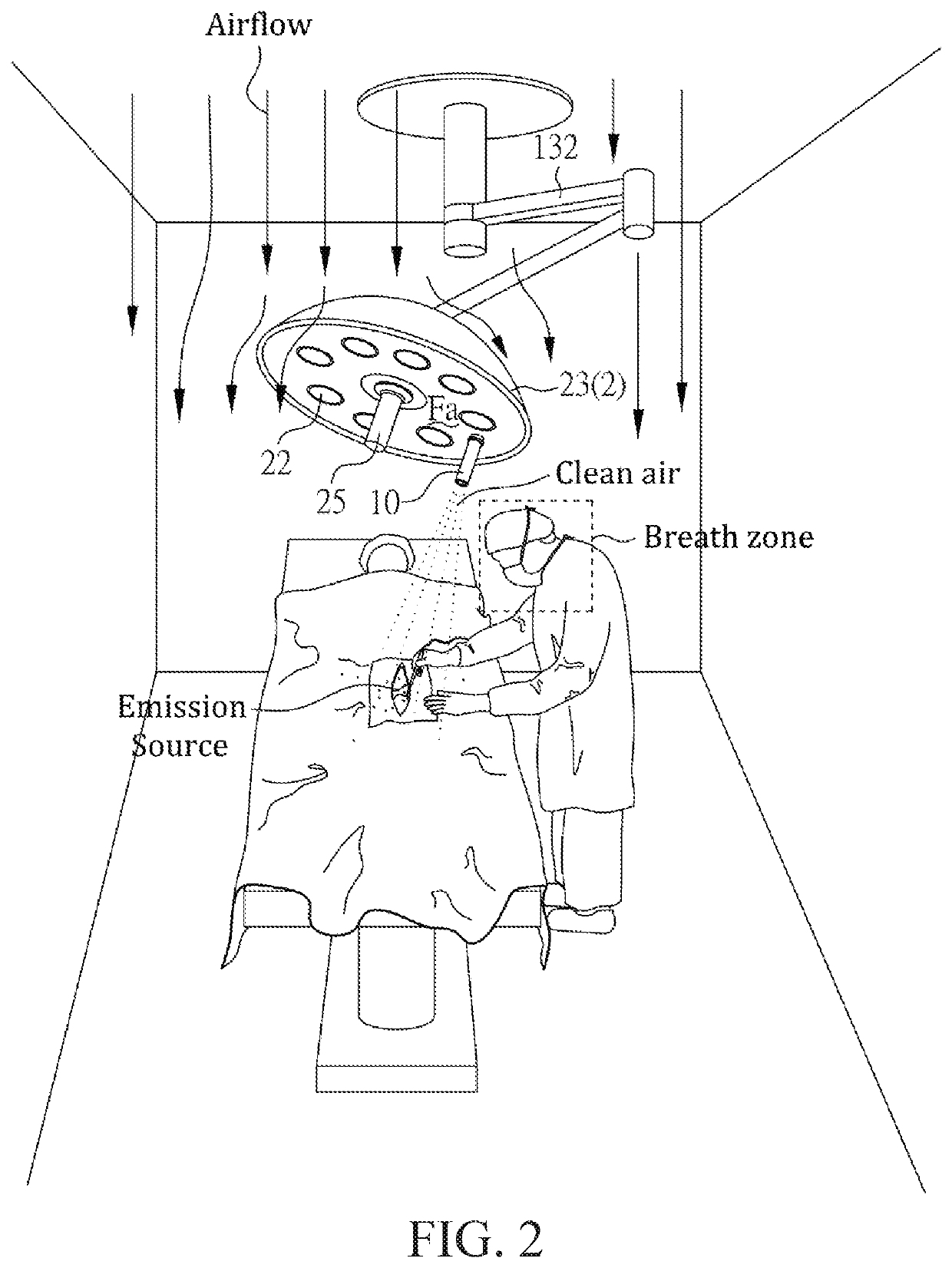
[0015]The surgical smoke removing device of the present invention can effectively reduce the air pollution concentration of the nearby pollution source and / or deliver clean air to the user's breathing zone. The user can choose to direct the airflow to the nearby pollution source and / or the breathing zone. In other embodiments, the user can also choose to suck air pollution from the emission source and / or deliver clean air to the user's breathing zone.

Problems solved by technology

Air pollution (including air pollutants or polluted air) can be generated from human activities such as cooking, surgery, smoking, drilling, or welding.
In particular, the use of an electrosurgical pencil in an operating room, the use of a dental drill in a dental clinic, or the use of a welding torch in welding factory can generate noticeable air pollution.
In particular, surgeons or medical personnel involved in the surgery may suffer from respiratory diseases due to inhalation of surgical smoke.
Therefore, the surgical smoke produced by the electrosurgical pencil can be harmful and should not be ignored.
However, some users may feel uncomfortable for they have to wear additional objects that cover their faces.
The base cannot be moved around easily.
Using the stand-alone air cleaner will increase labor costs, and more people will expose to the air pollution.
However, the portable air purifier has only one single inlet that can only capture the surgical smoke in a small area.
Meanwhile, the electrosurgical pencil attached with the portable air cleaner will take up more volume, and thus is inconvenient for the medical personnel to handle.
However, a stand-alone suction device may obstruct the dentist's sight, and thus affect the dental treatment.
In addition, the stand-alone suction device cannot provide enough protection to the medical personnel.
In the case of the welding factory, a welding process will produce a great amount of air pollution.
However, it may obscure the operator's field of vision and operation.

Method used


Image

  • Surgical smoke removing device
  • Surgical smoke removing device
  • Surgical smoke removing device

Examples


Embodiment Construction

[0043]Different embodiments of the present invention are provided in the following description. These embodiments are meant to explain the technical content of the present invention, but not meant to limit the scope of the present invention. A feature described in an embodiment may be applied to other embodiments by suitable modification, substitution, combination, or separation.

[0044]It should be noted that, in the present specification, when a component is described to have an element, it means that the component may have one or more of the elements, and it does not mean that the component has only one of the element, except otherwise specified.

[0045]Moreover, in the present specification, the ordinal numbers, such as “first” or “second”, are used to distinguish a plurality of elements having the same name, and it does not means that there is essentially a level, a rank, an executing order, or an manufacturing order among the elements, except otherwise specified. A “first” element...


PUM

PropertyMeasurementUnit
concentrationaaaaaaaaaa
poweraaaaaaaaaa
areaaaaaaaaaaa

Abstract

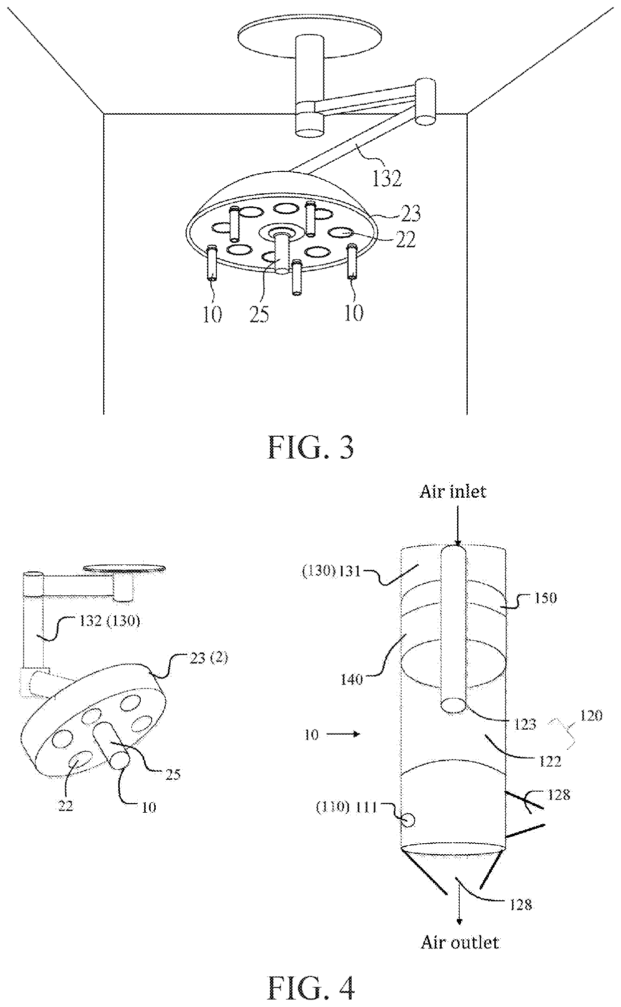
The present invention provides a surgical smoke removing device, which includes a smoke removing apparatus adapted to be connected to an application apparatus. The smoke removing apparatus includes an air cleaner, a stage, and a controller. The air cleaner has an inlet to suck in air, and an outlet to blow out clean air. The stage is configured to move the outlet of the air cleaner, such that the outlet targets at an emission source and/or a breathing zone of a user. The controller is connected to the air cleaner and the stage.

Description

CROSS REFERENCE TO RELATED APPLICATION[0001]This application claims the benefit of filing date of U.S. Provisional Application Ser. No. 62 / 841,833, entitled “AN APPLIANCE WITH AIR POLLUTION REDUCTION DEVICE” filed May 2, 2019 under 35 USC § 119(e)(1).BACKGROUND OF THE INVENTION1. Field of the Invention[0002]The present invention relates to an air pollution reduction device and, more particularly, to a surgical smoke removing device.2. Description of Related Art[0003]Air pollution (including air pollutants or polluted air) can be generated from human activities such as cooking, surgery, smoking, drilling, or welding. In particular, the use of an electrosurgical pencil in an operating room, the use of a dental drill in a dental clinic, or the use of a welding torch in welding factory can generate noticeable air pollution.[0004]In the case of the operating room, the electrosurgical pencil is often used for cutting, coagulating, desiccating, or fulgurating tissue. The surgical smoke is ...

Claims


Application Information

Patent Timeline
Patent Type & Authority Applications(United States)
IPC IPC(8): A61M1/00B01D46/44A61B18/14
CPCA61M2205/3303B01D46/44A61B18/14A61M1/0066A61B2218/008A61M2209/01A61M2205/3375A61M2205/75A61M2205/3306B01D2279/65A61B2218/006A61B18/00A61B2090/502B01D46/0047B01D2273/30
Inventor LIN, MING-YENGLIN, HUANN-SHYANGLAN, KUN-CHANKUO, YAO-LUNG
Owner NAT CHENG KUNG UNIV
Why Eureka
Try Eureka