
A barrier

a technology of barriers and walls, applied in the field of barriers, can solve the problems of significant handling problems, significant transportation difficulties, and increase the installation time of barriers, and achieve the effect of sufficient rigidity and sufficient rigidity

Pending Publication Date: 2020-11-05
SAFEROADS
View PDF16 Cites 1 Cited by
  • Summary
  • Abstract
  • Description
  • Claims
  • Application Information

AI Technical Summary

Benefits of technology

The present invention is based on the discovery that a solid block of ballast material can create a strong and affordable barrier that can be easily moved from a manufacturing site to a use location and quickly deployed as a functional barrier. The combination provides at least 80% of the resistance to collapse in response to vehicle impact.

Problems solved by technology

Whilst the above-described barriers function effectively as barriers, principally due to the substantial weights thereof, the substantial weights present significant transportation difficulties.
In addition, the need to fill water into and thereafter empty water from the plastics materials shell barriers presents significant handling issues and increases installation times considerably.
In addition, concrete barriers and water-filled barriers tend to crack when impacted by vehicles and lose functionality as a consequence and invariably cannot be used as barriers after a vehicle impact.
Moreover, the construction of these barriers, particularly concrete barriers and steel barriers, means that the barriers have no “give” on impact of a vehicle.

Method used


Image

  • A barrier
  • A barrier
  • A barrier

Examples


Embodiment Construction

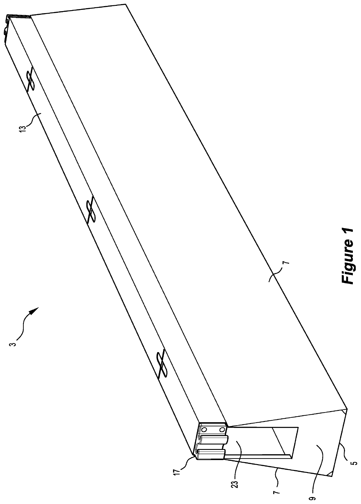
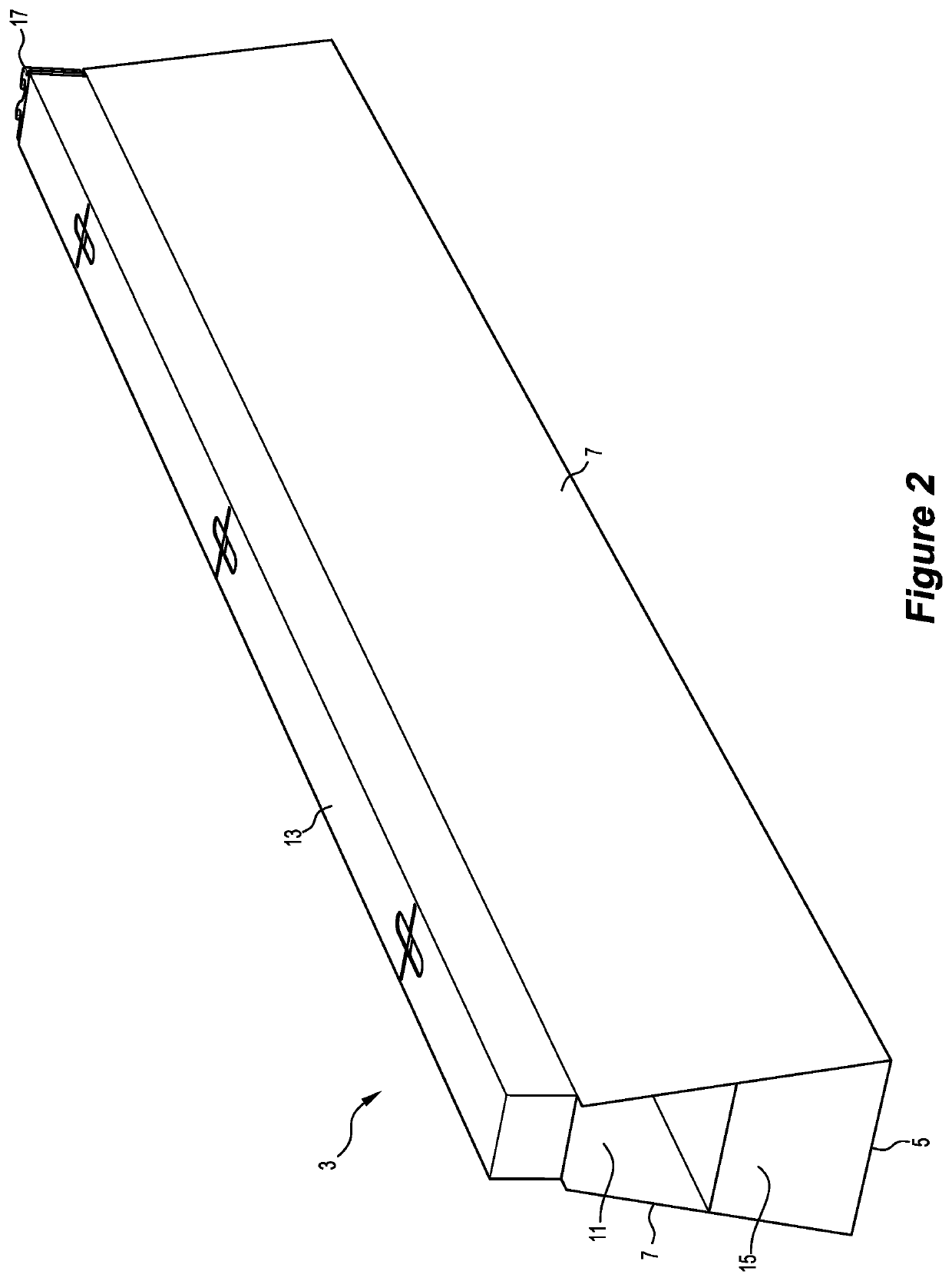
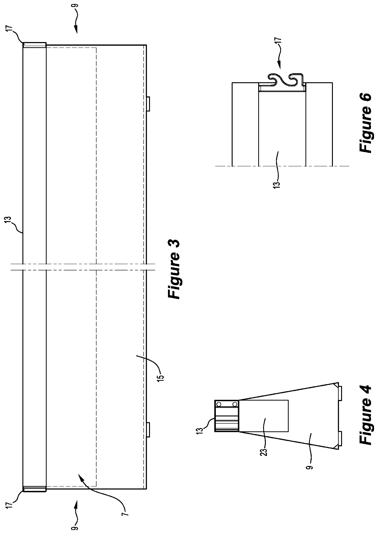
[0104]The embodiment of the elongate barrier 3 shown in the Figures is typically 5.8 m long, 900 mm high, 450 mm wide at the base and 200 mm wide at the top and weighs less than 2.6 tonnes and comprises:

[0105](a) an outer shell in an elongate lower section of the barrier 3 that defines a cavity 11 (see FIG. 2) that receive and contain a pourable, self-leveling, settable ballast material when the barrier 3 is being manufactured;

[0106](b) an upper structural element 13 extending along the length of the barrier,

[0107](c) a solid block 15 of a ballast material in the cavity 11 formed from the pourable settable ballast material which partially fills the cavity 11—see FIGS. 2 and 3; and

[0108](d) complementary connectors 17, such as described in Australian patent application 2015203840 in the name of the applicant, at the ends of the barrier 3 that allow a plurality of the barriers 3 to be connected together in end-to-end relationship.

[0109]The outer shell comprises a base wall 5, opposed ...


PUM


Abstract

An elongate barrier (3) comprises an outer shell in an elongate lower section of the barrier that defines a cavity (11) that receives and contains a pourable settable ballast material when the barrier is being manufactured. The barrier also comprises a solid block (15) of a ballast material in the cavity formed from the pourable settable ballast material.

Description

FIELD OF INVENTION[0001]The present invention relates to a barrier that is suitable for use in dividing an area into separate areas.[0002]More particularly, although by no means exclusively, the present invention relates to a barrier that is suitable for use in a large range of end-use applications that include, by way of example, use on roads for separating vehicles from other vehicles, separating vehicles from work zones so that work can be carried out safely in the work zones, and separating vehicles from pedestrians.[0003]The present invention relates particularly, although by no means exclusively, to a stand-alone, self-supporting, lightweight and readily transportable metal (which term includes metal alloy) barrier.[0004]The present invention also relates to a method of manufacturing the barrier.BACKGROUND OF THE INVENTION[0005]Known roadway barriers include:[0006](a) barriers made from concrete that rely on the weight of the concrete to function as barriers and typically weig...

Claims


Application Information

Patent Timeline
IPC IPC(8): E01F15/08E01F13/02
CPCE01F15/085E01F15/083E01F15/086E01F15/088E01F13/02
Inventor HOTCHKIN, DARREN
Owner SAFEROADS
Learn More