
Smart pressure relief valve

Active Publication Date: 2020-11-05
INTELLIHOT
View PDF0 Cites 0 Cited by
  • Summary
  • Abstract
  • Description
  • Claims
  • Application Information

AI Technical Summary

Benefits of technology

The present invention provides a device that includes a sensor to monitor pressure in a fluid system and a controller to establish an operating pressure zone based on the pressure signals over a period of time. The controller can generate an action if a new pressure signal is outside of the normal operation zone. The device can also include a valve actuator to operate the valve and a status light or audio emitter to alert stakeholders of the fluid system. The device can be integrated into a fluid heater or a flow sensor. The technical effects of the invention include no need for manual setting of relief pressure, providing pressure information prior to a pressure relieving event, and taking advantage of an existing sensor.

Problems solved by technology

Routine overpressure events can indicate serious problems in a fluid system, e.g., a fluid of the fluid system may be overheated which can cause bursting of the fluid conductors which carry the fluid which in turn can cause equipment damage, explosions of the fluid system if the overpressure is not relieved, e.g., if the pressure relief valve malfunctions, and even loss of lives.
While prior art pressure relief valves may function solely to relieve overpressure, they do not offer a glimpse into the reasons behind pressure relieving events.
If the relief pressure setting is disposed too high, a pressure relief valve may not relieve a damaging overpressure when it is expected to function.
If the relief pressure setting is disposed too low, a pressure relief valve may be activated unnecessarily too frequently.
Fima lacks a means for automatically setting the relief pressure of a pressure relief valve based on the operating pressure of the fluid system which its pressure relief valve is configured to safeguard.
Fima further lacks a pressure relief valve capable of operating jointly with a fluid supply device, e.g., a water heater, which already has sensors capable of reporting readings that can be used by a pressure relief valve.

Method used


Image

  • Smart pressure relief valve
  • Smart pressure relief valve
  • Smart pressure relief valve

Examples


Embodiment Construction

[0086]The term “about” is used herein to mean approximately, roughly, around, or in the region of. When the term “about” is used in conjunction with a numerical range, it modifies that range by extending the boundaries above and below the numerical values set forth. In general, the term “about” is used herein to modify a numerical value above and below the stated value by a variance of 20 percent up or down (higher or lower).

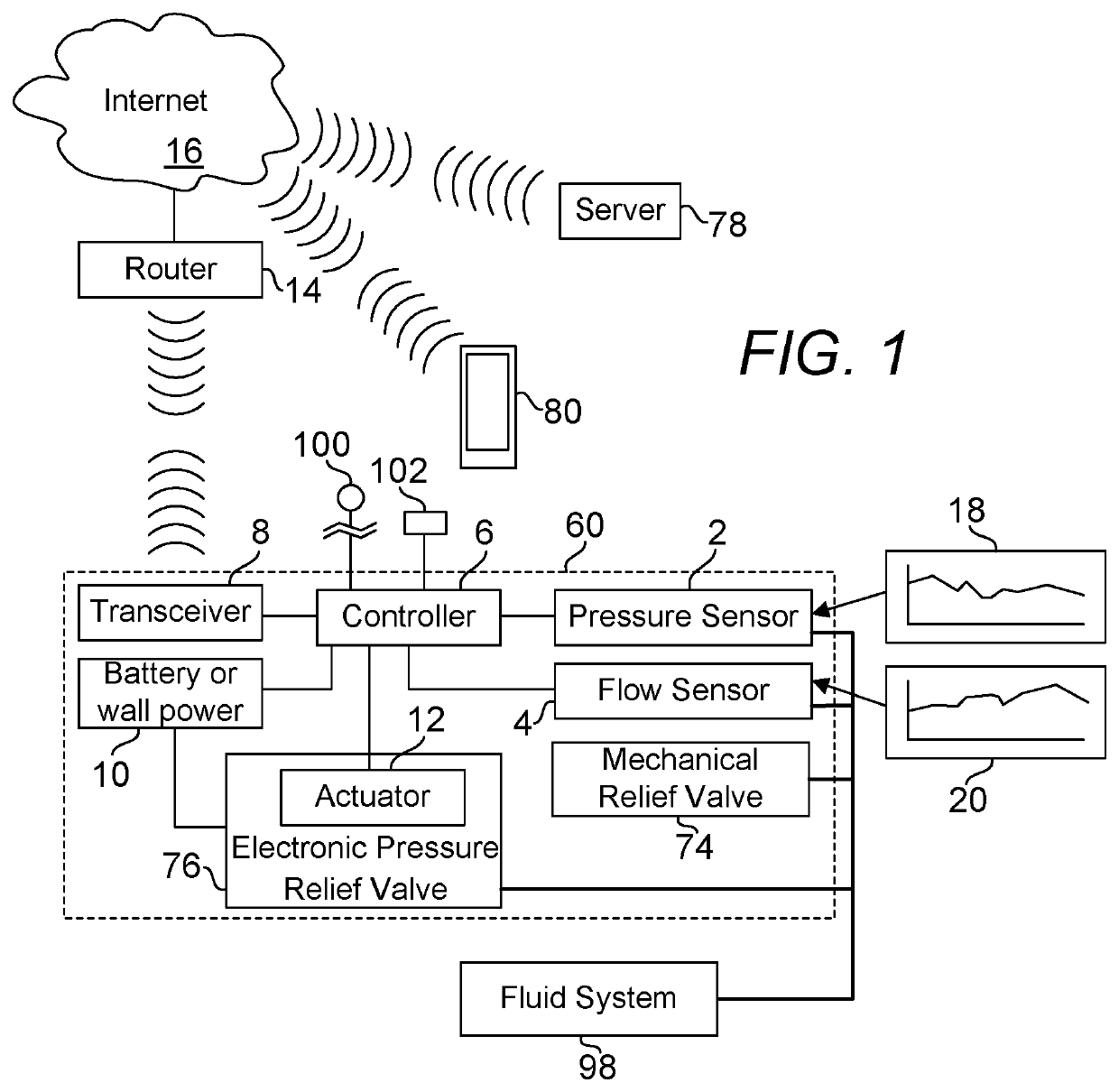
[0087]FIG. 1 is a diagram depicting a pressure relief valve adapted to carry out pressure relieving of a fluid system and also to detect and respond to a leak in the fluid system to which the valve is coupled. The term “pressure relief valve” is used herein to mean a device useful for relieving pressure of a fluid system and the device may include an electronic pressure relief valve 76, a mechanical pressure relief valve 74 or both. In case a mechanical pressure relief valve 74 is available in addition to the electronic pressure relief valve 76, the mechanical p...


PUM


Abstract

A device including: a sensor for monitoring a pressure of a fluid system to produce pressure signals over a period; and a controller configured for: receiving the pressure signals over the period; establishing an operating pressure zone corresponding to the pressure signals over the period, the operating pressure zone is representative of a normal operation zone of the fluid system, the normal operation zone defined by an area bounded by a low pressure level and high pressure level, wherein the high pressure level is disposed at a level at least at a maximum pressure of the pressure signals over the period and the low pressure level is disposed at a level at most at a minimum pressure of the pressure signals over the period.

Description

PRIORITY CLAIM AND RELATED APPLICATIONS[0001]This non-provisional application claims the benefit of priority from provisional application U.S. Ser. No. 62 / 842,549 filed May 3, 2019. Said application is incorporated by reference in its entirety.BACKGROUND OF THE INVENTION1. The Field of the Invention[0002]The present invention relates to a pressure relief valve. More specifically, the present invention is directed to a pressure relief valve configured for detecting and servicing an overpressure condition and also a leak in a fluid system to which the pressure relief valve is coupled.2. Background Art[0003]Mechanical pressure relief valves have been used for relieving overpressure of fluid systems for many years. With a mechanical pressure relief valve, when an overpressure event occurs, there are no indications that may be obtained from the mechanical pressure relief valve as to the event / s or causes preceding the overpressure event. Routine overpressure events can indicate serious p...

Claims


Application Information

Patent Timeline
IPC IPC(8): G05D16/20G05B19/416G08B21/18G08B7/06
CPCG08B7/06G05D16/2013G05B19/416G05B2219/37399G08B21/182G05B23/0235G05B23/027
Inventor DEIVASIGAMANI, SRIDHARAKASAM, SIVAPRASAD
Owner INTELLIHOT
Features
  • Generate Ideas
  • Intellectual Property
  • Life Sciences
  • Materials
  • Tech Scout
  • Unparalleled Data Quality
  • Higher Quality Content
  • 60% Fewer Hallucinations
Learn More