Extendable beam with slots

a technology of extendable beams and slots, applied in the direction of girders, transoms, walls, etc., can solve the problems of affecting the quality of wood frames, and requiring block repair for removal

Active Publication Date: 2020-12-10
QUICK HEADERS LLC
View PDF0 Cites 4 Cited by
  • Summary
  • Abstract
  • Description
  • Claims
  • Application Information

AI Technical Summary

Benefits of technology

[0009]Alternatively, a separate retention element may be used to maintain the two extendable members. For instance, an apertures may be milled. or premanufactured, o drilled into lateral, or side, walls of the housing and allow for passage of a pin or rod. A slot may also be milled, ore premanufactured, into the side walls of the extendable members. Such slots may allow for extension of the extendable members within a range to prevent the complete withdrawal of the extension member from the housing.

Problems solved by technology

Many times the wood frames are not the right size and have to be cut, fit, worked and reworked until the proper dimensions of the frame is made.
These frames are costly and are typically limited to a one time, single use because of the opening size.
Often installation and removal these frames require block repair and in interrupts a mason's job.
A wood frame may also leave rough finishings and limit access through the opening while the frame is in place and are not considered a very environmentally sensitive (or “green”) practice.

Method used


Image

  • Extendable beam with slots
  • Extendable beam with slots
  • Extendable beam with slots

Examples


embodiment 110

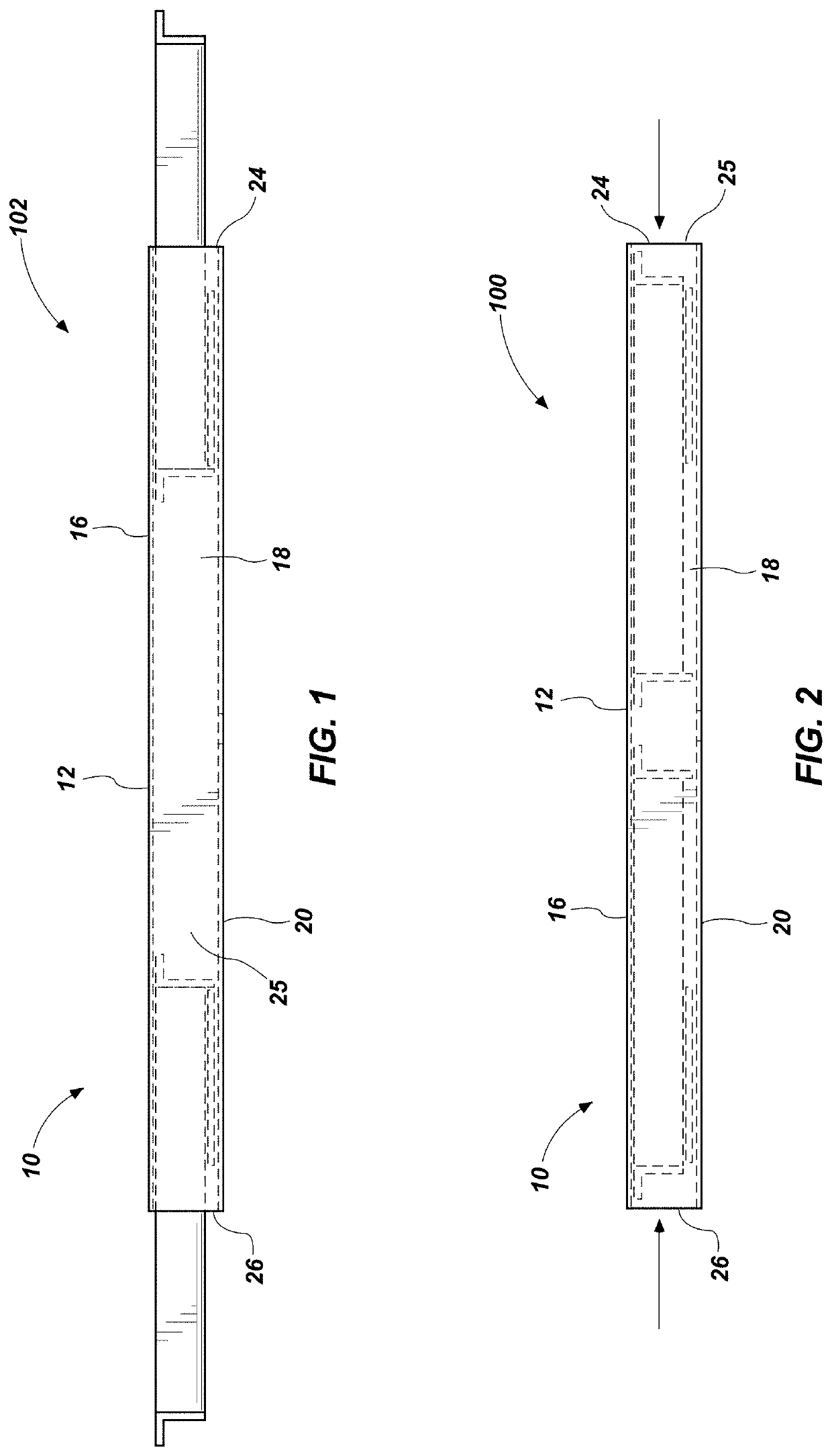
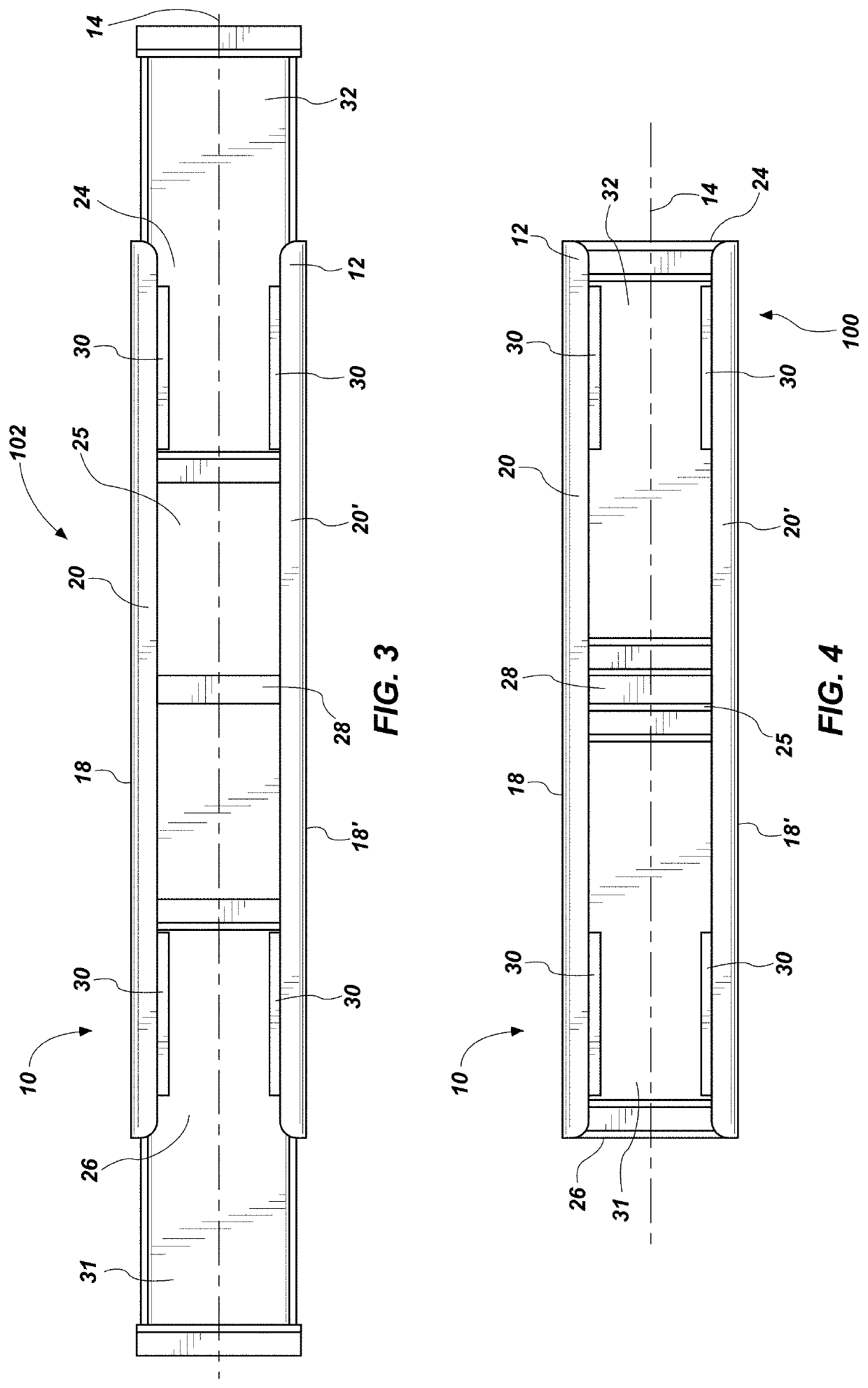
[0086]Referring to FIGS. 11-18, a system 210 is depicted with the housing 112 may be that as previously described herein. However, the extendable members 31, 32 may be substantially as previously described herein with the addition of the window 134. Rather than the system 10 comprising support members 30, this system 210 embodiment utilizes the same holes 152 and pin 130 wherein from the previous embodiment 110 wherein the pin 130 may act similarly as the support members 30 maintaining the extendable members 31, 32 in place as well as the pin 130 engaging with the proximal wall 38 to act as a stop, as similarly previously described.

[0087]In this embodiment the pin 130 may provide the same strength and stability as the support members 30 but with far less weight allowing for easier manipulation of the system 110 or system 210.

[0088]Referring to FIGS. 19-22, the extendable member 132 may comprise an alternate flange that may comprise an angle. A flange 164 may comprise the same elemen...

first embodiment

[0092]Referring to FIGS. 31-42 similar examples of angled flanges are provided utilizing the extendable members 32 described in the system 10 with the exception of the window 134 also contemplated herein. Similar angles to the previous embodiments are shown with angles of 11°, 22° and 45° respectively. These embodiments may not include the slots 154 as these embodiments may be intended for use with the alternate system 210 but may also be utilized in the first described system 10.

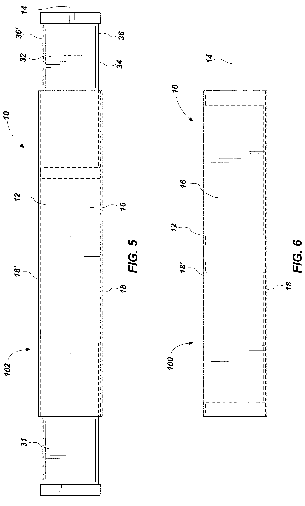
[0093]The dimensions of the system may vary as well. The housing 12 may be anywhere from 2 feet (or roughly 0.6 meters) to 42 feet (or roughly 13 meters) in length. The width of the housing 12 may be 4 to 8 inches (or roughly 10 cm to 21 cm). The height of the housing 12 may be 2 to 4 inches (or roughly 5 cm to 11 cm). The length of the extendable members 31, 32, may vary but may be in the range of 12 to 18 inches (or roughly 30 cm to 46 cm), with the extendable members 31, 32 being capable of extending 6 t...


PUM


Abstract

A system for traversing an opening of a construction element the system including a elongated housing with two extendable elements configured to reside at least partially within the housing. The extendable elements may extend beyond the housing and may include flanges or ledges which may engage the ends of a construction element, which may be a wall, and thus allow the system to traverse the opening of a construction element, such as a window or door. The system may allow a user to easily manipulate the system to fit a plurality of openings and reuse the system a countless number of times.

Description

CROSS-REFERENCE TO RELATED APPLICATIONS[0001]This application incorporates by reference U.S. patent application Ser. No. 15 / 672,143 entitled EXTENDABLE BEAM filed Aug. 8, 2017, now U.S. Pat. No. 10,280,618.TECHNICAL FIELD[0002]This disclosure relates generally to an extendable beam methods and systems for masonry use in spanning and carrying a load of an opening. These systems relate more specifically to the use of a single beam over two vertical supports to create an opening, such as a window or doorway or other architectural element.RELATED ART[0003]In masonry, forms are often used to create windows, doorways or openings. These forms can be called many different things such as frames, bucks, headers, girders, joists and the like. These forms are often made of simple wood (2×4s or 2×6s) and built to hopefully fit within the space needed. Many times the wood frames are not the right size and have to be cut, fit, worked and reworked until the proper dimensions of the frame is made. A...

Claims


Application Information

Patent Timeline
Patent Type & Authority Applications(United States)
IPC IPC(8): E04C3/07
CPCE04B2/02E04C2003/0413E04C3/07E04C2003/023E06B1/02E04C2003/0473E04C3/005
Inventor KELLY, SCOT RYAN
Owner QUICK HEADERS LLC
Why Eureka
Try Eureka