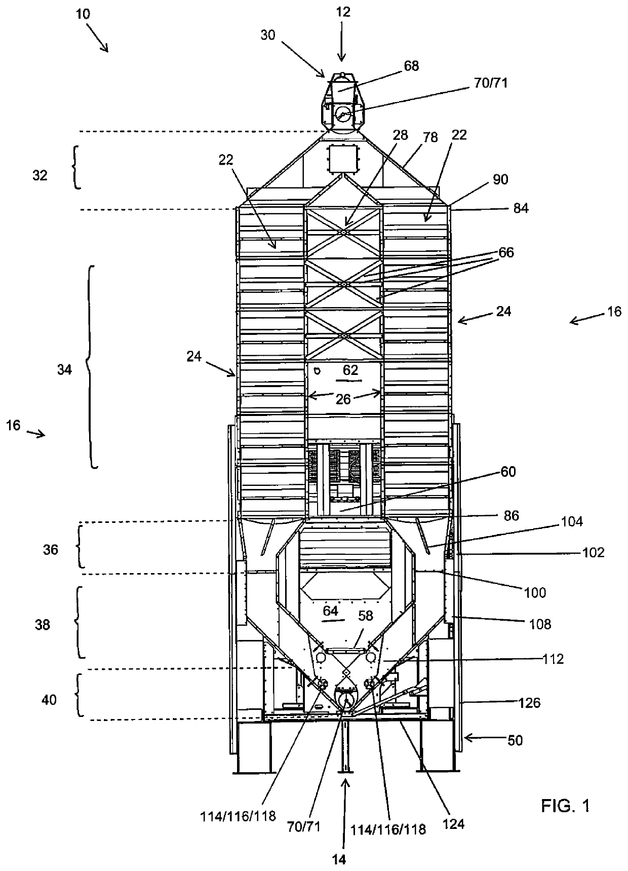
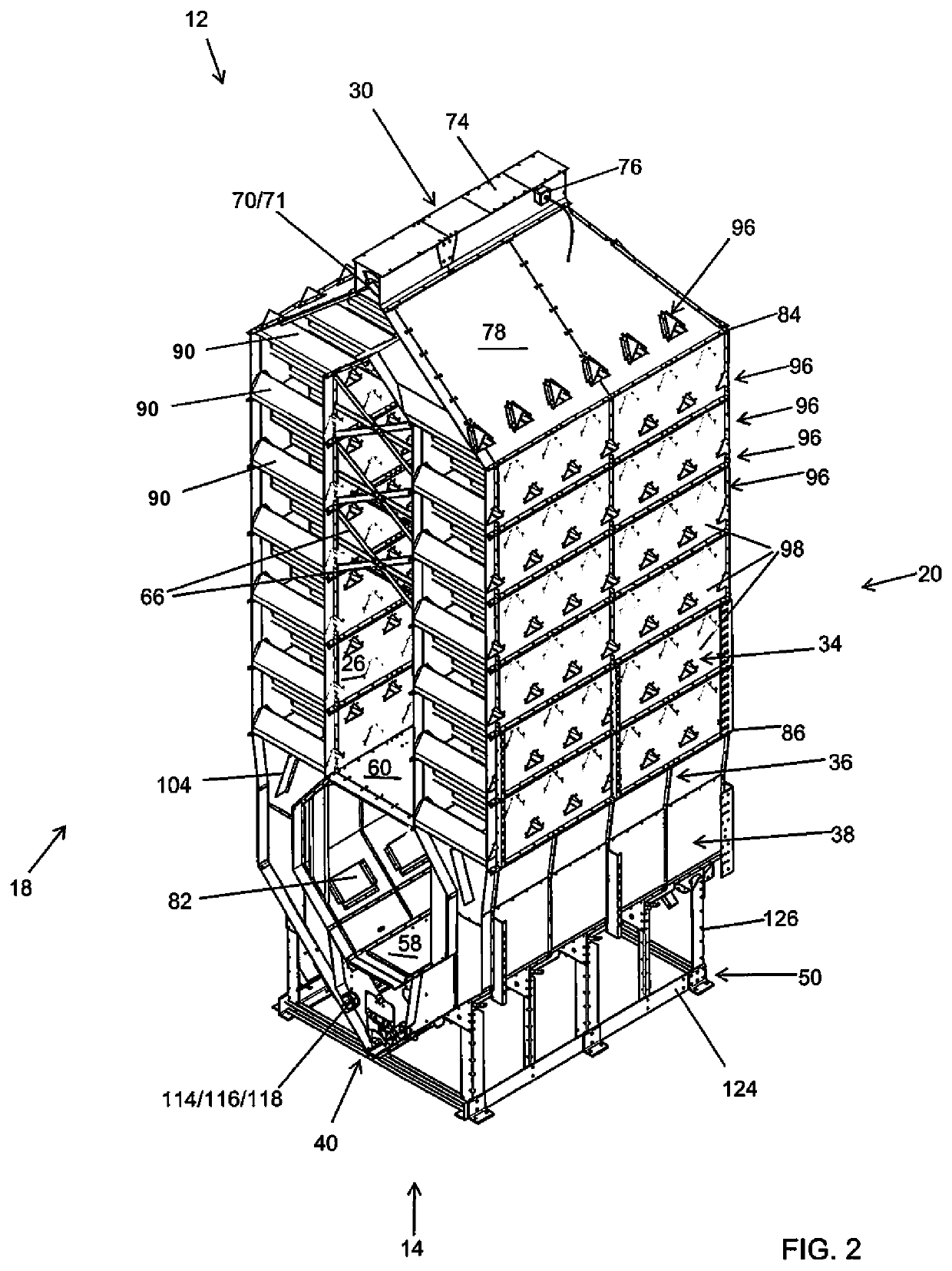
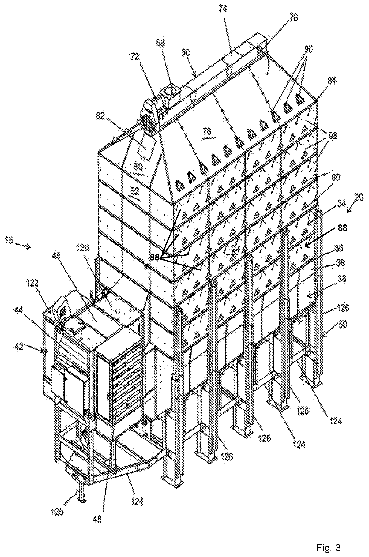
Bridge reducing mixed-flow grain dryer with cross-flow vacuum cool heat recovery system

Active Publication Date: 2020-12-10
SUKUP MFG
View PDF0 Cites 1 Cited by
  • Summary
  • Abstract
  • Description
  • Claims
  • Application Information

AI Technical Summary

Benefits of technology

The present invention is a mixed-flow grain dryer with a cross-flow vacuum cool heat recovery system. It uses a loading system, heating section, heated and pressurized air, wet holding section, cooling section, and an unloading system. The system combines the benefits of mixed-flow heating and cross-flow vacuum cooling to provide gentle and efficient drying. The fan pulls air through the grain column in the cooling section, heating the air while cooling the grain, which is then blown into the heat plenum to pressurize it. The technical effects of the invention include gentle drying, high efficiency, and reduction of energy consumption.

Problems solved by technology

If grain is stored in bulk with a moisture content that is too high, the grain will spoil.
Optimally drying grain is a particularly complex, difficult and delicate matter.
However, it is also undesirable to overly dry grain.
Overly drying grain is wasteful in various ways.
Overly drying grain consumes additional and unnecessary fuel used to dry the grain beyond the moisture content level that is needed for stable storage.
Overly drying grain often takes additional and unnecessary time to dry the grain beyond the moisture content level that is needed for stable storage.
Overly drying grain can damage the grain by causing it to be burned, cracked or otherwise damaged, which can reduce the value of the grain.
Overly drying grain can reduce the test weight of the grain thereby causing a deduction in the price of the grain when it is sold.
For these and other reasons, overly drying grain is undesirable.
As such, optimally drying grain requires striking a delicate balance between overly drying grain on one side, and not drying grain enough on the other side.
However, all of the presently available grain dryers suffer from various disadvantages.
One disadvantage of cross-flow grain dryers is that they are relatively harsh on grain.
This is because the grain toward the interior side of the grain columns is often exposed to high levels of heat which can cause the interior-positioned grain to crack, burn, and / or be overly dried.
Another disadvantage of cross-flow grain dryers is that the grain within the grain columns tends to dry in an uneven manner.
Another disadvantage of cross-flow is that they tend to require relatively high operating pressures and high air-flow.
Another disadvantage of cross-flow grain dryers is that they tend to consume a lot of fuel, or said another way they are energy inefficient.
Another disadvantage of cross-flow grain dryers is the screens tend to get covered and plugged with fines from the grain which affects the operational characteristics of the grain dryer as well as requires periodic cleaning.
For these and other reasons, cross-flow grain dryers suffer from many disadvantages and are undesirable to use.
One disadvantage of mixed-flow grain dryers is that they do not allow for heat recovery and as such they waste energy and consume unnecessary fuel.
Another disadvantage of mixed-flow grain dryers is that each column requires its own unload system.
Another disadvantage of mixed-flow grain dryers is that they are susceptible to bridging of grain in grain columns.
For these and other reasons, mixed-flow grain dryers suffer from many disadvantages and are undesirable to use.

Method used


Image

  • Bridge reducing mixed-flow grain dryer with cross-flow vacuum cool heat recovery system
  • Bridge reducing mixed-flow grain dryer with cross-flow vacuum cool heat recovery system
  • Bridge reducing mixed-flow grain dryer with cross-flow vacuum cool heat recovery system

Examples


Embodiment Construction

[0073]In the following detailed description of the embodiments, reference is made to the accompanying drawings which form a part hereof, and in which is shown by way of illustration specific embodiments in which the disclosure may be practiced. The embodiments of the present disclosure described below are not intended to be exhaustive or to limit the disclosure to the precise forms in the following detailed description. Rather, the embodiments are chosen and described so that others skilled in the art may appreciate and understand the principles and practices of the present disclosure. It will be understood by those skilled in the art that various changes in form and details may be made without departing from the principles and scope of the invention. It is intended to cover various modifications and similar arrangements and procedures, and the scope of the appended claims therefore should be accorded the broadest interpretation so as to encompass all such modifications and similar ...


PUM


Abstract

An improved grain dryer is presented having a mixed-flow heating section having a plurality of inlet ducts connected to the plenum that facilitate air flow into the grain column from the heated and pressurized heat plenum, and a plurality of exhaust ducts connected to openings in the exterior wall that facilitate air flow out of the grain column. Outer most ducts of the inlet and exhaust ducts, which are positioned closest to end walls of the grain column, are configured to reduce bridging or grain between the outer most ducts and the end walls of the grain column.

Description

CROSS REFERENCE TO RELATED APPLICATIONS[0001]This application is a continuation in part of U.S. Utility application Ser. No. 16 / 258,158 which was filed on Jan. 25, 2019 entitled “MIXED-FLOW GRAIN DRYER WITH CROSS-FLOW VACUUM COOL HEAT RECOVERY SYSTEM”, which is a continuation in part of U.S. Utility application Ser. No. 15 / 131,865 which was filed on Apr. 18, 2016, the entirety of which is incorporated herein fully by reference herein.[0002]This application claims priority to U.S. Provisional Patent Application. 62 / 937,627, which was filed on Nov. 19, 2019 entitled “BRIDGE REDUCING MIXED-FLOW GRAIN DRYER WITH CROSS-FLOW VACUUM COOL HEAT RECOVERY SYSTEM”, the entirety of which is incorporated herein fully by reference herein.FIELD OF THE DISCLOSURE[0003]This disclosure relates to generally to the grain handling, grain storage and grain conditioning arts. More specifically and without limitation, this disclosure relates to the grain drying arts. More specifically and without limitation...

Claims


Application Information

Patent Timeline
IPC IPC(8): F26B17/14
CPCF26B17/1425F26B2200/06Y02P70/10
Inventor HEILSKOV, CASEY SCOTTHARTWIG, KERRYRAU, TYLERMARTIN, VERNON
Owner SUKUP MFG
Why Eureka
Try Eureka