Air compressor

Active Publication Date: 2015-10-08
CHOU WEN SAN
View PDF7 Cites 10 Cited by
  • Summary
  • Abstract
  • Description
  • Claims
  • Application Information

AI Technical Summary

Benefits of technology

The present invention provides an air compressor with a plastic cylinder and frame that can be easily mounted and secured, and a cooling fan to dissipate heat from the piston motion. The compressor has two tubular projections on the top wall of the cylinder, with one containing a first seal ring and the other a second seal ring. A spring is used to force a sealing means against the second seal ring to secure the bore defined by the tubular projections. The technical effects of this invention include increased operational security and reduced manufacturing costs.

Problems solved by technology

Although conventional air compressors, which are made of metal, would not cause deformation on the cylinder when it is subject to the heat generated from the reciprocating motion of the piston, the manufacturing cost is high.
Another disadvantage of conventional air compressors is that the sealing means, such as a valve plug or a resilient sheet, disposed between the air storage container and the cylinder is prone to lose its original sealing function after they have been used for a period of time.
For this reason, the air compressing function of conventional air compressors cannot be well maintained.
The applicant also has successfully modified an air compressor that was originally poor in performance.

Method used


Image

  • Air compressor
  • Air compressor
  • Air compressor

Examples


first embodiment

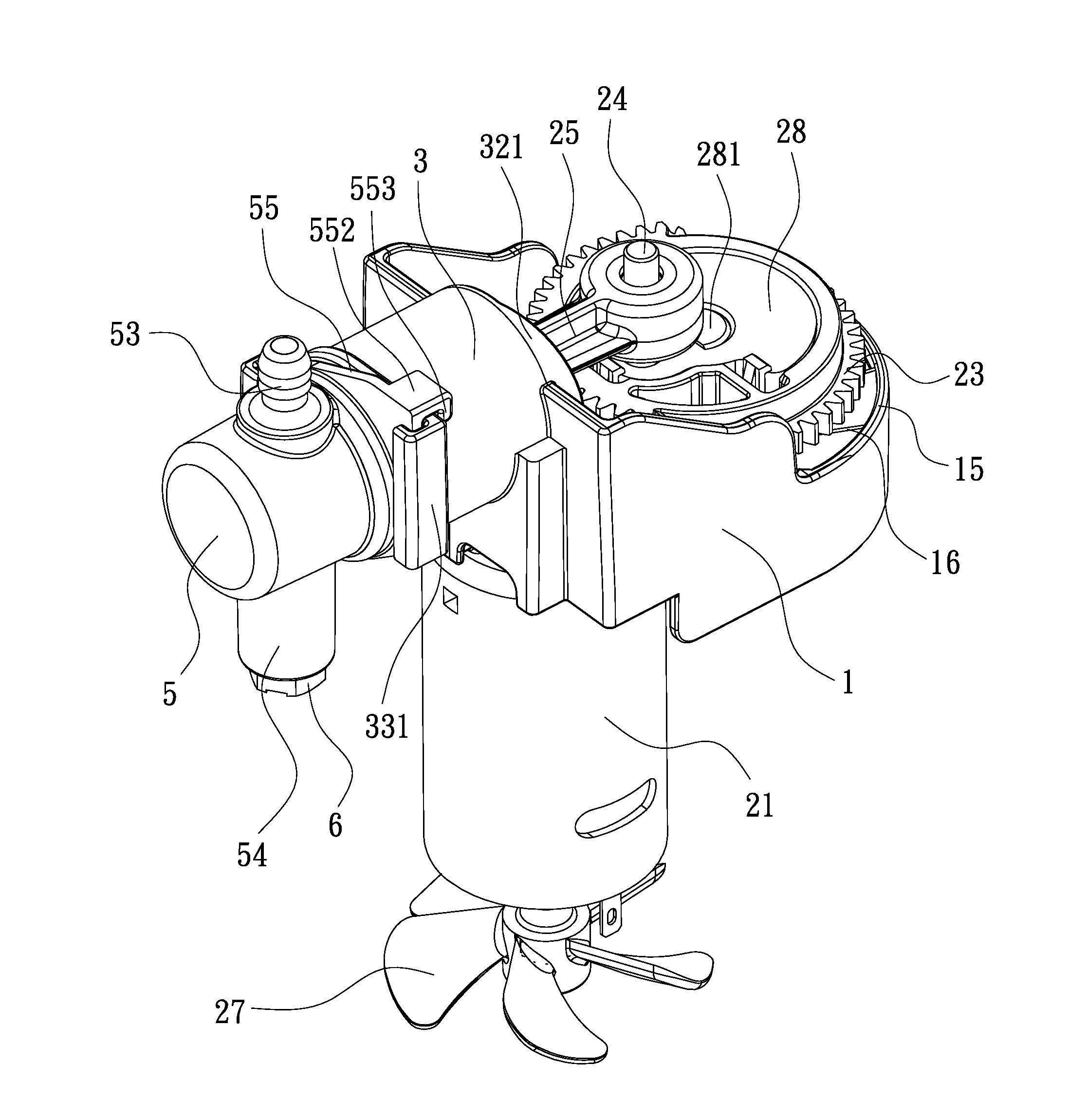
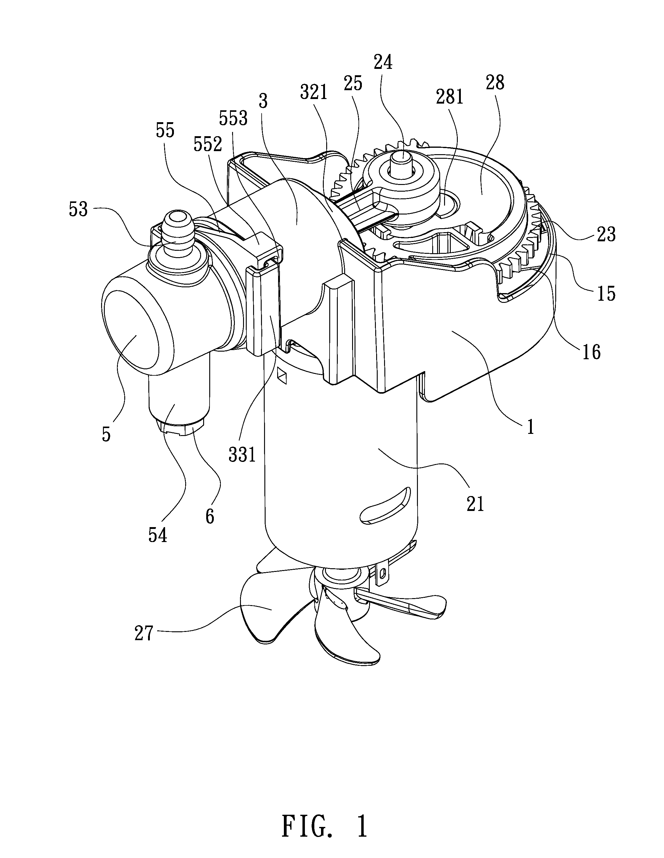
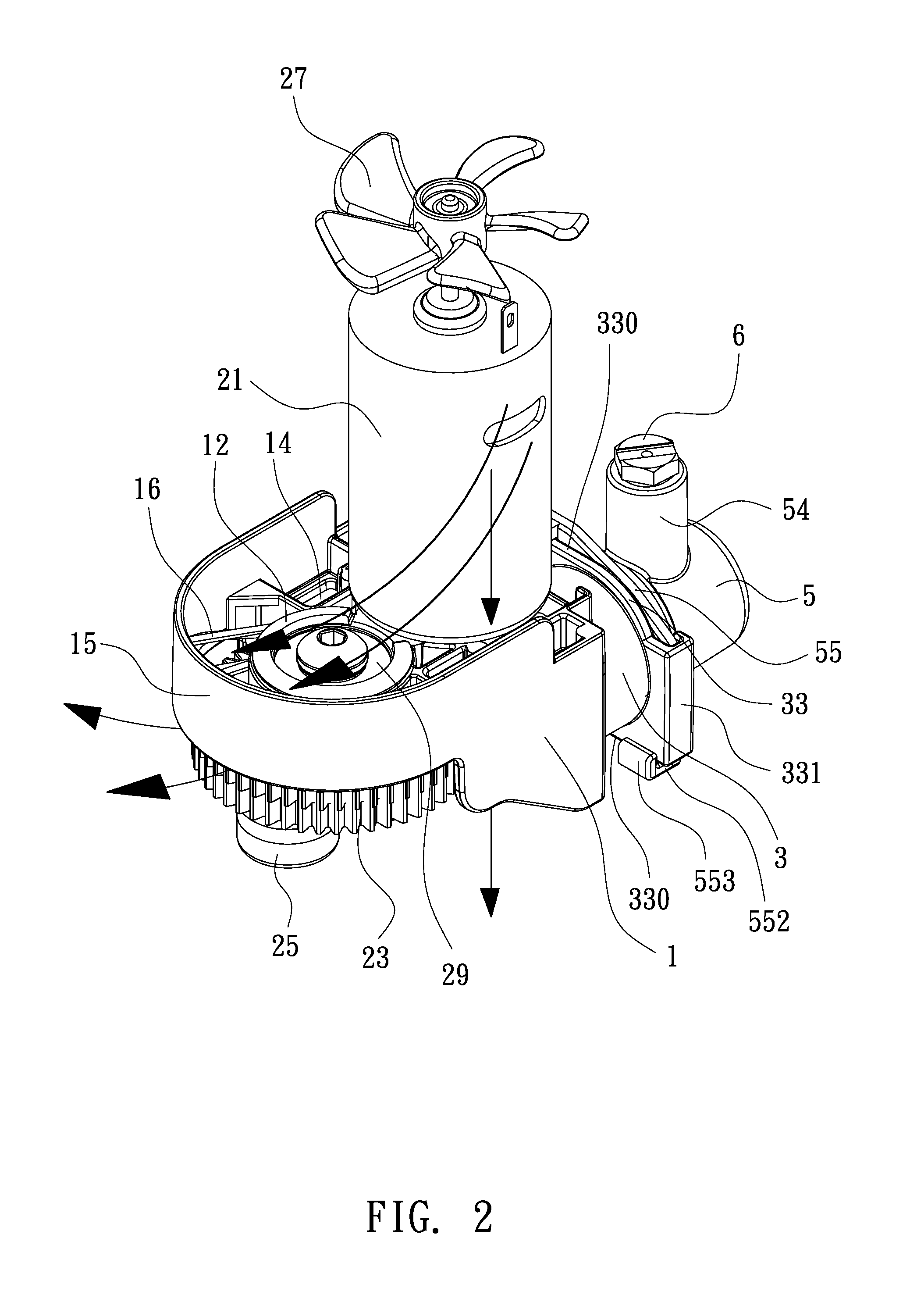
[0034]Referring first to FIGS. 1 through 5, an air compressor according to the present invention is shown, wherein a cylinder 3 is fitted with a piston body 25 having a piston head 26, a main frame 1 is used for mounting a motor 21 that can drive the piston body 25 to conduct reciprocating motion within the cylinder 3. In particular, the cylinder 3 and the main frame 1 are integrally formed of plastic. The main frame 1 has a first portion 11 and a second portion 12 (see FIG. 5). The first portion 11 mounts the motor 21 that is fitted with a small gear 22 at one end and a cooling fan 27 at the other end. The second portion 12 fixes a bearing 29 in place. The large gear 23 is provided with a counterweight 28 being fixed with a crankpin 24. A crankshaft 281 is fixed at one end to the counterweight 28 and mounted at the other end to the bearing 29. The piston body 25 is pivotally mounted to the crankpin 24. The large gear 23 are mounted to the main frame 1 such that the small gear 22 en...

second embodiment

[0037]The second annular groove 371 of the second tubular projection 37 can only be formed by plastic molding, so that the second tubular projection 37 cannot be made from metal. The air storage container 5 has an open bottom 51 and defines therein an inner space 52. The open bottom 51 of the air storage container 5 is formed with a second coupling means 55 that includes two substantially opposite lateral plates 551 extending outwardly from the surrounding wall of the air storage container 5. One side of each lateral plate 551 of the air storage container 5 is formed with a second holding portion that includes a base section 552 perpendicular to the associated lateral plate and an end section 553 parallel to the associated lateral plate to define a second recess 550 therebetween (see also FIG. 8). The air storage container 5 is provided at its peripheral inner surface with a plurality of spaced-apart ribs 59. There is a gap 591 existed between two adjacent ribs 59. Furthermore, the ...


PUM


Abstract

An air compressor includes an air storage container, a cylinder fitted with a piston body and a main frame for mounting a motor. The cylinder and the main frame are integrally formed of plastic. The air storage container is detachably mounted to the cylinder. The main frame is provided with though holes for guiding the air flow, generated by a cooling fan, to flow through the main frame. The main frame is formed with two lateral walls and a bottom wall to form a U-shaped wind collecting shell. The second portion of the main frame is held by multiple radial braces, which facilitates the air flow being introduced through the main frame for rapidly dissipating the heat generated from the reciprocating motion of the piston body, so that the operational security can be increased. The non-metal air compressor may lead to a reduction of the manufacturing cost and the weight.

Description

TECHNICAL FIELD OF THE INVENTION[0001]The present invention relates to an air compressor and, more particularly, to an air compressor that includes an air storage container, a cylinder, and a main frame for mounting a motor, wherein the air storage container, the cylinder, and the main frame are made of plastic, the cylinder is formed integrally with the main frame, and the air storage container is detachably mounted to the cylinder.DESCRIPTION OF THE PRIOR ART[0002]Generally, an air compressor employs a motor to drive a piston to conduct reciprocating motion within a cylinder for producing compressed air in the cylinder. The compressed air can be transferred to an air storage container, which is usually provided with one or more outlets. Functional elements, such as safety valve and relief valve, can be installed at the outlets. Alternatively, a connecting means, such a hose can be connected to one outlet to allow the compressed air within the storage container to be delivered to a...

Claims


Application Information

Patent Timeline
IPC IPC(8): F04B39/06F04B35/04
CPCF04B35/04F04B39/066F04B39/121F04B39/125F04B39/127F04B39/14F04B53/08F05C2225/00F04B35/01F04B39/00F04B39/06F04B53/00
Inventor CHOU, WEN-SAN
Owner CHOU WEN SAN
Why Eureka
Try Eureka