Antenna array tilt and processing to eliminate false detections in a radar system

a radar system and array technology, applied in the field of antenna array tilt and processing to eliminate false detections in radar systems, can solve the problems of false detections, power, cost requirements, relative large number of antenna elements,

Active Publication Date: 2020-12-10
GM GLOBAL TECH OPERATIONS LLC
View PDF0 Cites 2 Cited by
  • Summary
  • Abstract
  • Description
  • Claims
  • Application Information

AI Technical Summary

Benefits of technology

[0003]In one exemplary embodiment, a method of identifying an object using a radar system includes arranging an array of antenna elements into two or more subarrays with a tilt angle relative to each other. Each of the two or more subarrays includes two or more antenna elements among the array of antenna elements. The method also includes receiving reflected signals at each of the two or more ...

Problems solved by technology

However, arranging antenna elements at no more than half-wavelength (½λ) spacing over a wide aperture results in a relatively large number of antenna elements and correspond...

Method used


Image

  • Antenna array tilt and processing to eliminate false detections in a radar system
  • Antenna array tilt and processing to eliminate false detections in a radar system
  • Antenna array tilt and processing to eliminate false detections in a radar system

Examples


Embodiment Construction

[0029]The following description is merely exemplary in nature and is not intended to limit the present disclosure, its application or uses. It should be understood that throughout the drawings, corresponding reference numerals indicate like or corresponding parts and features.

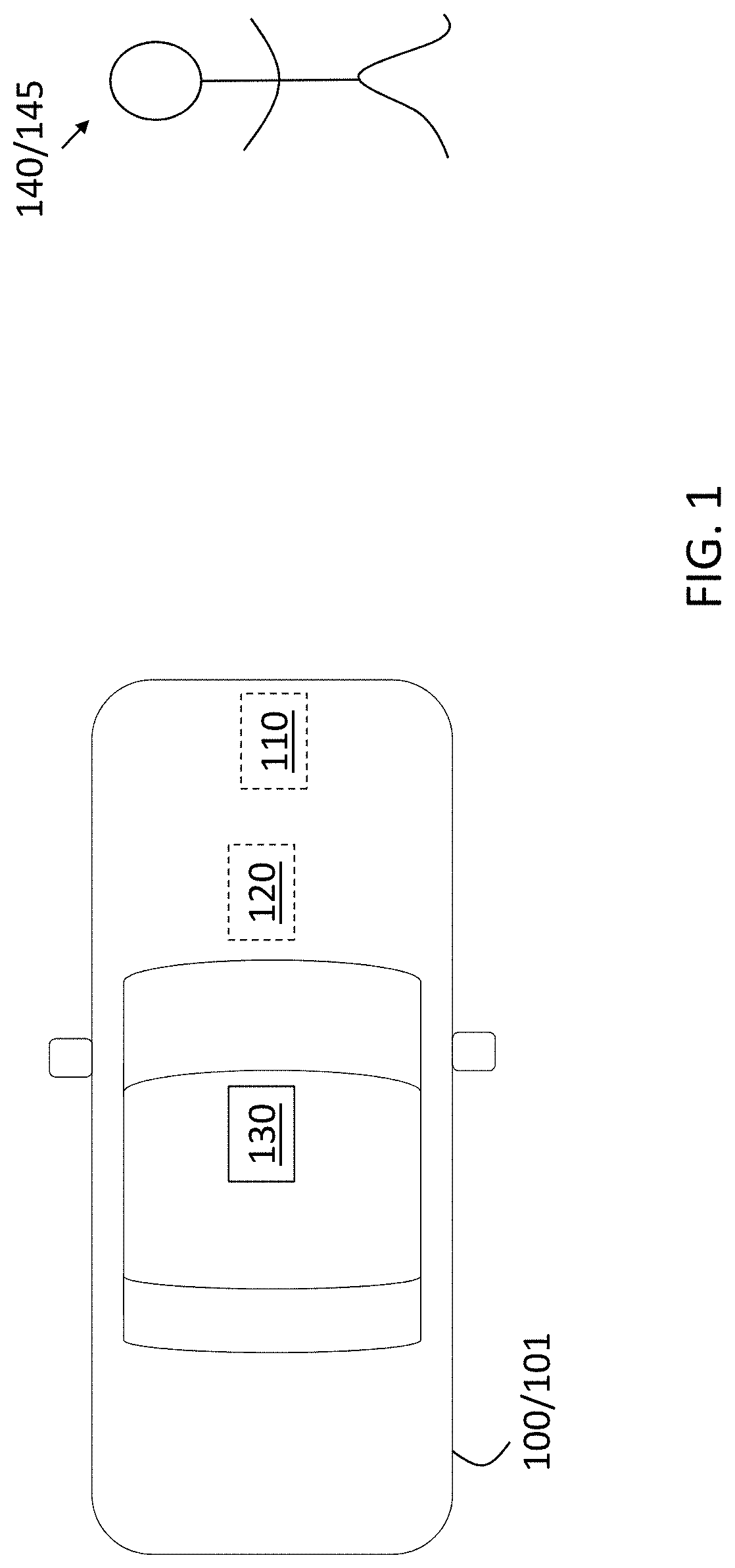
[0030]As previously noted, a wide aperture of antenna elements in a radar system facilitates obtaining information from a wide field of view. However, a dense array of antenna elements over that width with the requisite half-wavelength spacing between them is costly in terms of components and complexity. At the same time, a more sparse array of antenna elements, which are spaced apart by more than a half-wavelength, results in decreased angular resolution and false detections due to ambiguity in determining the angle of arrival of reflections. Embodiments of the systems and methods detailed herein relate to antenna array tilt and processing to eliminate false detections in a radar system. The antenna array is d...


PUM


Abstract

Systems and methods to identify an object using a radar system involve arranging an array of antenna elements into two or more subarrays with a tilt angle relative to each other. Each of the two or more subarrays includes two or more antenna elements among the array of antenna elements. A method includes receiving reflected signals at each of the two or more subarrays resulting respectively from transmitting transmit signals from the two or more subarrays, and processing the reflected signals at each of the two or more subarrays to obtain an amplitude associated with each azimuth angle in a range of azimuth angles. A location of the object is determined as the azimuth angle in the range of azimuth angles at which the amplitude exceeds a threshold value.

Description

INTRODUCTION[0001]The subject disclosure relates to antenna array tilt and processing to eliminate false detections in a radar system.[0002]Radar systems and other sensors are increasingly used in vehicles (e.g., automobiles, trucks, farm equipment, construction equipment, automated factories) to obtain information about the vehicle and its surroundings. A radar system may identify objects in the path of the vehicle, for example, and facilitate autonomous or semi-autonomous vehicle operation. A radar system having a wide field of view (i.e., wide aperture) facilitates obtaining more information about the surroundings of the vehicle. However, arranging antenna elements at no more than half-wavelength (½λ) spacing over a wide aperture results in a relatively large number of antenna elements and correspondingly high complexity, power, and cost requirements. Yet, a sparser array of antenna elements over the same aperture width results in angle ambiguity that leads to false detections. A...

Claims


Application Information

Patent Timeline
IPC IPC(8): G01S7/28H01Q3/26G01S13/93
CPCH01Q3/26G01S13/931G01S7/2813G01S13/42
Inventor BIALER, ODEDJONAS, AMNON
Owner GM GLOBAL TECH OPERATIONS LLC
Why Eureka
Try Eureka