Apparatus and a method for visualizing target objects in a fluid-carrying pipe

a technology of target objects and video cameras, which is applied in the field of apparatus and a method for providing an accurate image of a target object in a fluid-carrying pipe, can solve the problems of high cost, high use cost, and inability to see in such an environment by using video cameras,

Active Publication Date: 2010-03-09
VISURAY TECH
View PDF11 Cites 40 Cited by
  • Summary
  • Abstract
  • Description
  • Claims
  • Application Information

AI Technical Summary

Benefits of technology

[0019]A downhole unit 10 includes a cooling unit (not shown), a light source 1 and a sensor unit 1a consisting of a scatter limiting aperture 5, a scintillator / amplifier unit 6 and a charge coupled device (CCD) or a photodiode assembly (PDA) 7. The light source 1 produces high-energy photons 2 having a wavelength greater than 1×10⁻¹¹ m (0.01 nanometers). Preferably, embodiments use light sources that emit high-energy photons having a wavelength between 1×10⁻¹¹ m (0.01 nanometers) and 1×10⁻⁸ m (10 nanometers). Rays having a wavelength between 1×10⁻⁸ m and 1×10⁻¹¹ m have the desired effect both in terms of image quality and the energy level for penetration of relevant fluids.
[0017]The FIGURE is a schematic diagram illustrating an apparatus according to some embodiments of the invention.
[0036]Alternatively, images may be obtained following a delayed transmission of the recorded measurement data, either through causing a suitable delay in the measurement data in a continuous signal transmission, or by storing the measurement data in a suitable medium for retrieval at a later time, e.g. after retrieving the measuring apparatus from the measurement area.
[0027]The apparatus also provides the possibility of gathering spectral energy information from the incoming photons 4. These photons 4 contain information regarding the electronic energy level of the atoms in the target object. Thus, the acquired data can be compared with known material data. This means that an operator of the equipment according to the invention can point and click on the target object such as it appears in the generated images and by so doing, obtain information regarding the material to be examined, such as scale (contamination), reservoir structure inspection, the effect of perforations and more.
[0038]Some embodiments of the invention may include components that are required to generate images from a fluid-carrying pipe in which known video camera technology can not be used due to the inability of ordinary light to penetrate the fluid contents of the pipe.

Problems solved by technology

The environment in exploration and production wells for oil and gas generally prohibits the use of video cameras due to the presence of saline solutions, mud, hydrocarbons and other substances that prevent the passage of visible light.
Consequently, the possibility of seeing in such an environment by using a video camera is highly limited, due to the normal mixture of substances in the well.
This very often results in time-consuming and costly inspections of well formations and equipment, and also fishing operations directed at the removal of unwanted objects in exploration and production wells.
Currently there exists no apparatus capable of seeing the targets under such conditions.
Short-wave radiation in the form of gamma rays (−11 m) has a wavelength and an energy level that gives sufficient image quality, but unfortunately requires a radiation source in the form of a radioactive material, which is out of the question in the environment of exploration and productions wells for oil and gas.

Method used


Image

  • Apparatus and a method for visualizing target objects in a fluid-carrying pipe
  • Apparatus and a method for visualizing target objects in a fluid-carrying pipe

Examples


Embodiment Construction

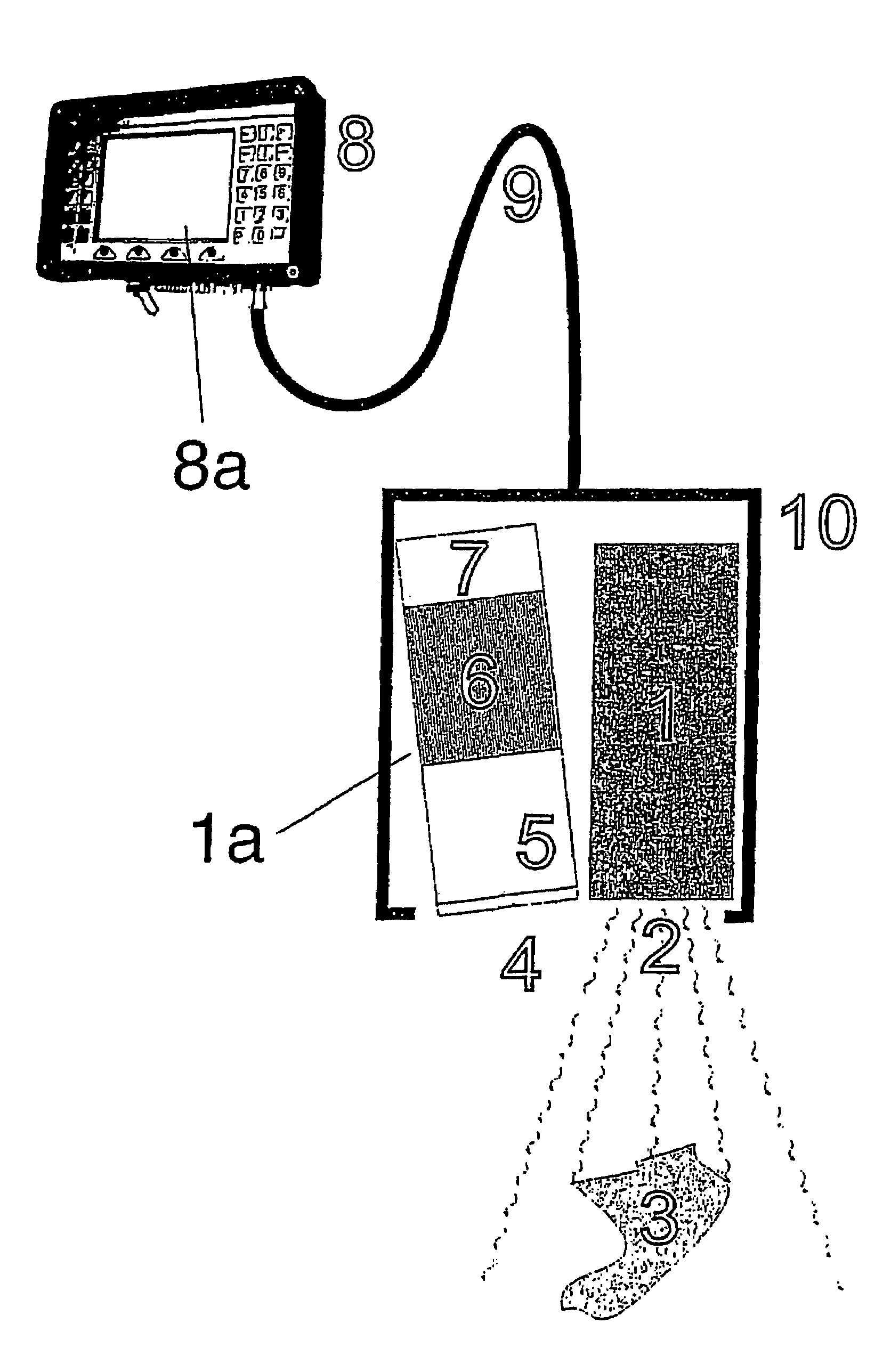
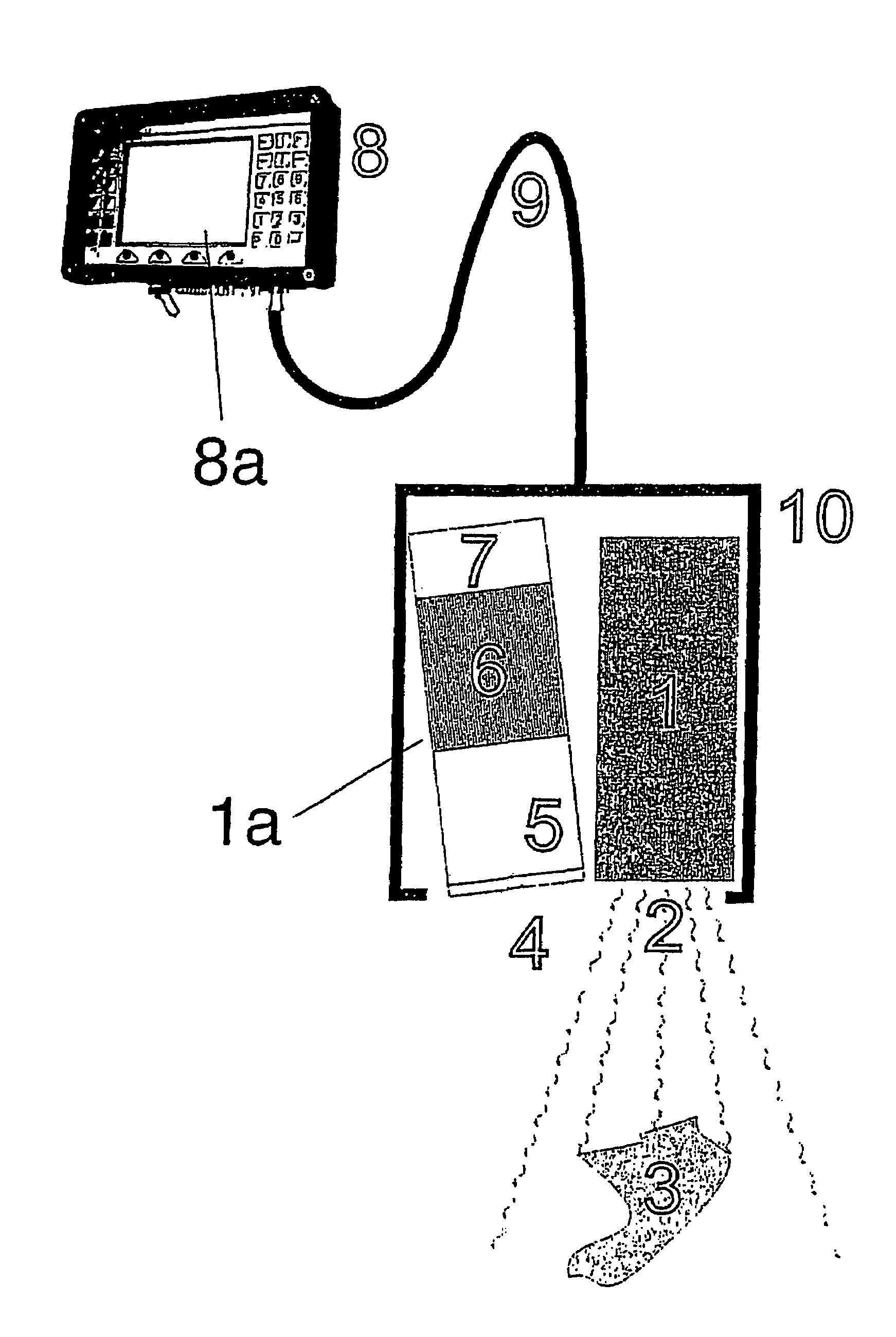
[0018]The FIGURE is a schematic diagram illustrating an apparatus according to some embodiments of the invention.

[0019]A downhole unit 10 includes a cooling unit (not shown), a light source 1 and a sensor unit 1a consisting of a scatter limiting aperture 5, a scintillator / amplifier unit 6 and a charge coupled device (CCD) or a photodiode assembly (PDA) 7. The light source 1 produces high-energy photons 2 having a wavelength greater than 1×10⁻¹¹ m (0.01 nanometers). Preferably, embodiments use light sources that emit high-energy photons having a wavelength between 1×10⁻¹¹ m (0.01 nanometers) and 1×10⁻⁸ m (10 nanometers). Rays having a wavelength between 1×10⁻⁸ m and 1×10⁻¹¹ m have the desired effect both in terms of image quality and the energy level for penetration of relevant fluids.

[0020]The photons illuminate a downhole target object 3. Photons that result from bireflection 4 (i.e. reflection, decelerating radiation, scatter and / or Compton scatter) from the electron density of a ...


PUM


Abstract

An apparatus for recording and displaying images of and identifying material types in a target object in a fluid carrying conduit includes a downhole unit. The downhole unit includes a controllable light source, the controllable light source structured to emit high energy photons. The downhole unit further includes a sensor unit structured to detect the high energy photons that are backscattered from the target object and to generate signals in response to the detected high energy photons. The apparatus also includes a control and display unit that includes a signal transmitter and a viewing screen structured to display at least one two-dimensional image that is generated using the signals from the sensor unit.

Description

CROSS-REFERENCE TO RELATED APPLICATIONS[0001]This U.S. national stage application claims priority from International Application No. PCT / NO2004000252, filed on 26 Aug. 2004, which in turn claims priority from Norwegian Patent Application No. 20043504, filed on 23 Aug. 2004, and Norwegian Patent Application No. 20033832, filed on 29 Aug. 2003. International Application No. PCT / NO2004000252 and Norwegian Patent Application Nos. 20043504 and 20033832 are incorporated by reference.BACKGROUND[0002]1. Technical Field[0003]This disclosure relates to an apparatus and a method for providing an accurate image of a target object in a fluid-carrying pipe and more particularly, to an apparatus and method for providing an accurate image of a target object in an exploration or production well or in a pipeline carrying fluids such as hydrocarbons or aqueous liquids, and provides the opportunity of accurately determining which types of material said target object is composed of.[0004]2. Description ...

Claims


Application Information

Patent Timeline
Patent Type & Authority Patents(United States)
IPC IPC(8): G01V5/08G01V5/12E21BE21B47/00
CPCE21B47/0002E21B47/002E21B47/09G01N23/00
Inventor RAMSTAD, EINARTEAGUE, PHIL
Owner VISURAY TECH
Why Eureka
Try Eureka