
Paper cutting device for kiosk printer and kiosk printer equipped with the same

a technology of paper cutting device and kiosk printer, which is applied in the direction of printing, other printing devices, etc., can solve the problems of difficult to separate the movable cutter from the fixed cutter, the movable cutter cannot be opened, and the conventional kiosk printer, etc., and achieves the effect of convenient replacement or mounting

Active Publication Date: 2020-12-17
BIXOLON
View PDF0 Cites 2 Cited by
  • Summary
  • Abstract
  • Description
  • Claims
  • Application Information

AI Technical Summary

Benefits of technology

The disclosed invention proposes a paper cutting device for a kiosk printer that allows for easy replacement or mounting of roll paper when a paper jam occurs or roll paper is replaced. The device includes a movable cutter that performs cutting while being raised in a vertical direction, and the cutter is lowered when the paper movement path is opened to prevent safety-related accidents. Additionally, the invention includes a protective feature to prevent exposure of the rail to external environments, and guide members that can provide supporting force at set locations and can be easily moved by external force.

Problems solved by technology

In the common kiosk printer, a movable cutter configured to cut roll paper cuts roll paper while moving in a downward direction or a horizontal direction, and thus it is difficult to separate the movable cutter from a fixed cutter.
Accordingly, the conventional kiosk printer has a problem of inconvenience in that when a paper jam occurs in the process of cutting or transferring roll paper, the movable cutter cannot be opened, and paper needs to be replaced or removed in the state in which only the platen roller or the introduction portion of the container has been opened.
Furthermore, the conventional kiosk printer also has a problem of inconvenience in that when roll paper is replaced, the roll paper needs to be mounted by being inserted between the movable cutter and the fixed cutter.
Accordingly, this kiosk print has a problem in that it is inconvenient to replace or mount paper.
Meanwhile, common printers generate the paper dust of paper in the process of cutting roll paper.
When paper dust is repeatedly generated and accumulated on the operating portion of a platen roller or a thermal head, a problem arises in that a breakdown of a component is caused.
Furthermore, conventional kiosk printers have a problem in that when a jam of roll paper occurs, they cannot be operated until an administrator removes the jam.
Meanwhile, in the case of common kiosk printers, guide portions configured to guide roll paper are installed with the gap therebetween fixed, and thus a problem arises in that the gap between the guide portions cannot be adjusted.
In this printing unit, the gap between guide portions configured to guide paper is fixed, and thus a limitation occurs in that only paper having a single width can be used.
Furthermore, according to the related technology, the height of a paper fastening part configured to fasten roll paper cannot be adjusted, and thus a problem arises in that roll paper cannot be mounted when the size of the roll paper is large.
Furthermore, the related technology has a problem in that it is difficult to check the residual amount of roll paper which is coupled to the paper fastening part.
Moreover, the related technology has a problem in that when a problem, such as a paper jam or a paper shortage, occurs while a user is printing a receipt or the like using a kiosk printer and thus it is necessary to repair the internal configuration of the printer, it is inconvenient to directly open the cover of the printer for repair or a general user cannot directly repair the configuration even when the cover is opened.

Method used


Image

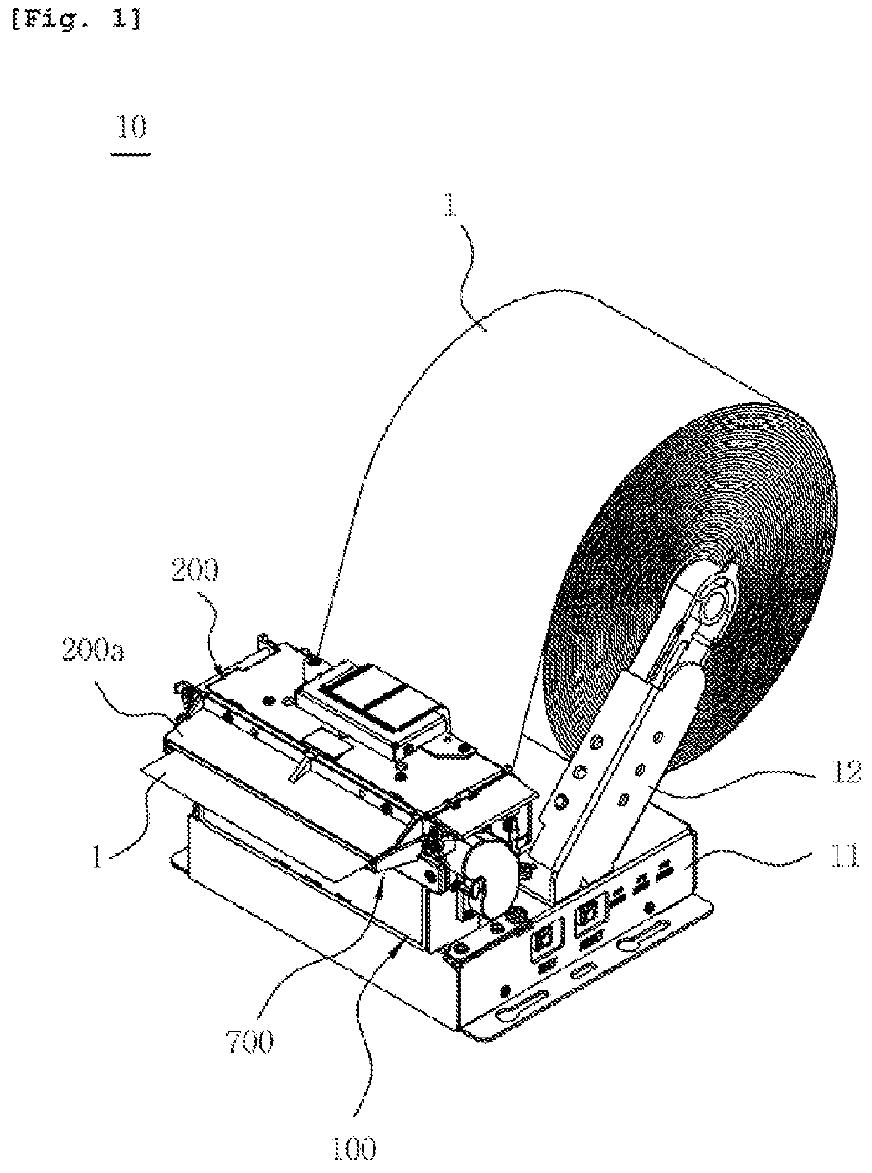
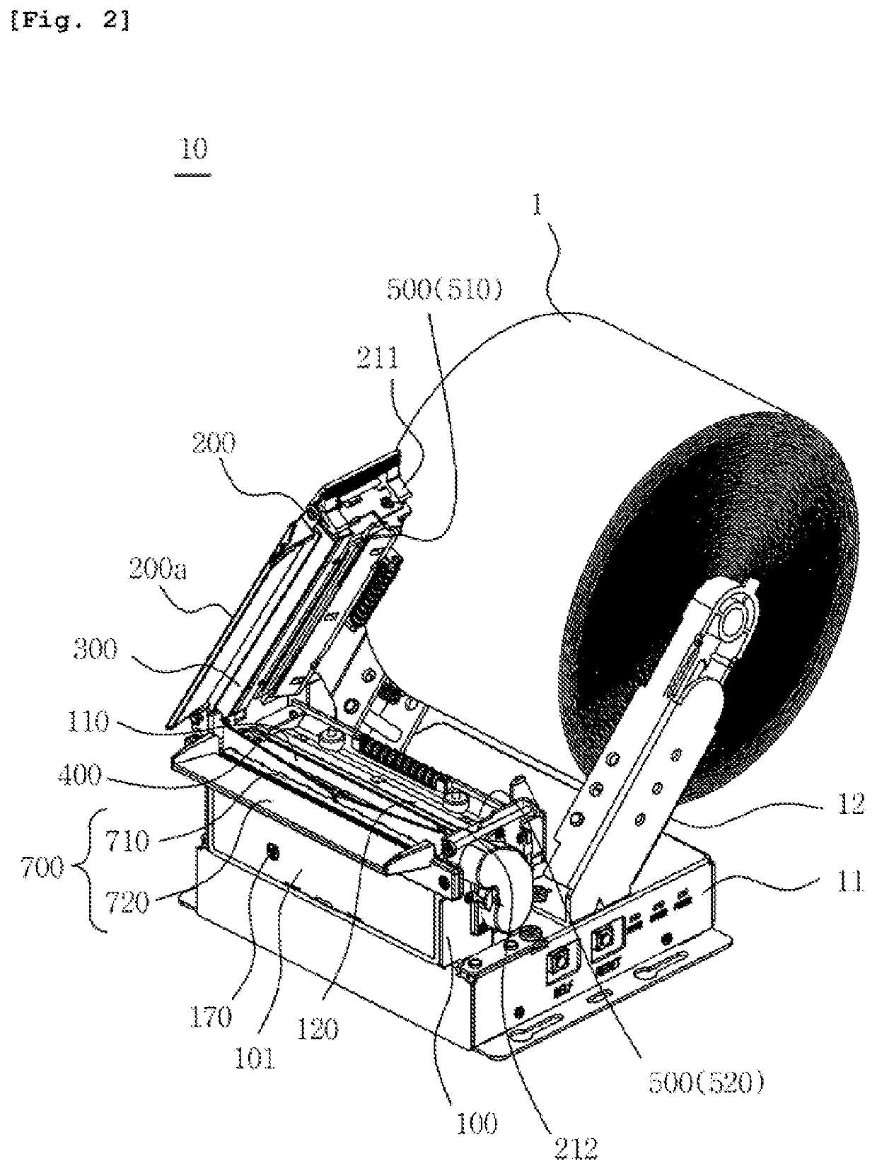
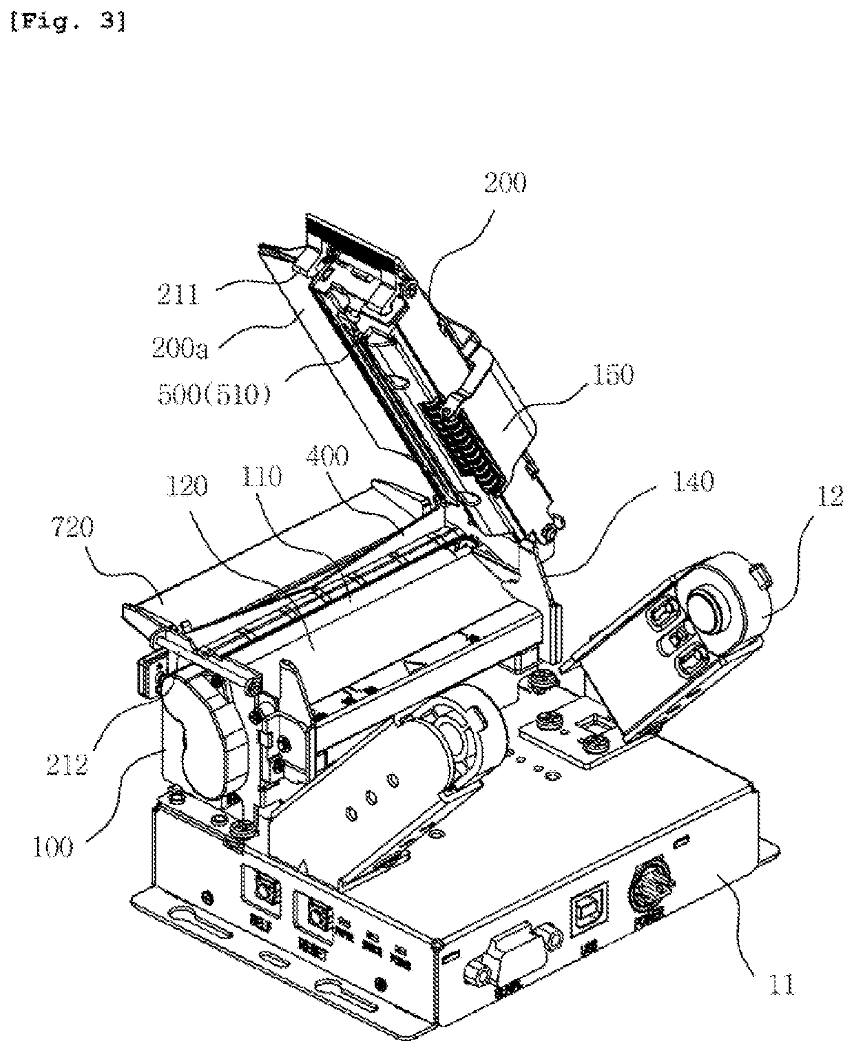
  • Paper cutting device for kiosk printer and kiosk printer equipped with the same
  • Paper cutting device for kiosk printer and kiosk printer equipped with the same
  • Paper cutting device for kiosk printer and kiosk printer equipped with the same

Examples


Embodiment Construction

[0054]Various embodiments will be described in detail below with reference to the accompanying drawings. The following embodiments may be modified to various different forms and then practiced. In order to more clearly illustrate the features of the embodiments, detailed descriptions of items which are well known to those having ordinary skill in the art to the following embodiments pertain will be omitted. In the drawings, portions unrelated to the following description will be omitted. Throughout the specification, like reference symbols will be assigned to like portions.

[0055]Throughout the specification and the claims, when one component is described as being “connected” to another component, the one component may be “directly connected” to the other component or “electrically connected” to the other component through a third component. Furthermore, when any portion is described as including any component, this does not mean that the portion does not exclude another component bu...


PUM


Abstract

The paper cutting device includes: a lower frame configured such that a platen roller and a thermal head are disposed on the top surface thereof and provide a paper movement path and a drive unit is contained therein; an upper frame configured to form the paper movement path in association with the lower frame, and to open the paper movement path; a fixed cutter configured to be disposed on the upper frame, and to cut the roll paper; a movable cutter configured to be disposed on the lower frame, to cut the roll paper, and to allow the roll paper to move; and a jam control unit configured to detect a jam of the roll paper, and to detect the opening of the paper movement path and lower the movable cutter.

Description

CROSS-REFERENCE TO RELATED APPLICATION[0001]This application claims the benefit of Korean Patent Application No. 10-2019-0069777 filed on Jun. 13, 2019, No. 10-2019-0096792 filed on Aug. 8, 2019, No. 10-2020-0021029 filed on Feb. 20, 2020, which is hereby incorporated by reference herein in its entirety.BACKGROUND1. Technical Field[0002]Embodiments disclosed herein relate generally to a paper cutting device for a kiosk printer and a kiosk printer equipped with the same, and more specifically to a paper cutting device for a kiosk printer, which is capable of cutting roll paper on which information is printed, and a kiosk printer equipped with the paper cutting device, a paper guide device for a kiosk printer, which is capable of guiding roll paper through movement while supporting both ends of the roll paper in its widthwise direction, and a kiosk printer equipped with the paper guide device, and a method for automatically opening and closing the cover of a printing apparatus and a p...

Claims


Application Information

Patent Timeline
IPC IPC(8): B41J11/70B41J11/00B41J15/04B41J2/32
CPCB41J11/706B41J11/006B41J15/042B41J2/32B41J11/70
Inventor KIM, JIN GWANKIM, JIN KOOK
Owner BIXOLON
Learn More