Radio-frequency module

a radio-frequency module and module technology, applied in the field of radio-frequency modules, can solve problems such as module malfunction, and achieve the effects of preventing performance degradation of radio-frequency modules, enhancing the functionality of radio-frequency modules, and suppressing nois

Active Publication Date: 2020-12-17
MURATA MFG CO LTD
View PDF0 Cites 1 Cited by
  • Summary
  • Abstract
  • Description
  • Claims
  • Application Information

AI Technical Summary

Benefits of technology

[0015]According to this configuration, since the components are mounted on both sides of the wiring board, it is possible to further enhance the functionality of the radio-frequency module.
[0016]The radio-frequency module may further include a shield film which covers at least the side surfaces of the first sealing resin layer and the side surfaces and the facing surface of the second sealing resin layer. According to this configuration, it is possible to suppress noise due to electromagnetic waves from the outside and prevent performance degradation of the radio-frequency module.

Problems solved by technology

The exposed surface of the resin layer has a role of insulating the periphery of the connection terminal; however, if plating is deposited on this surface, a short circuit between the connection terminals may occur, which causes malfunction of the module.

Method used


Image

  • Radio-frequency module
  • Radio-frequency module
  • Radio-frequency module

Examples


first embodiment

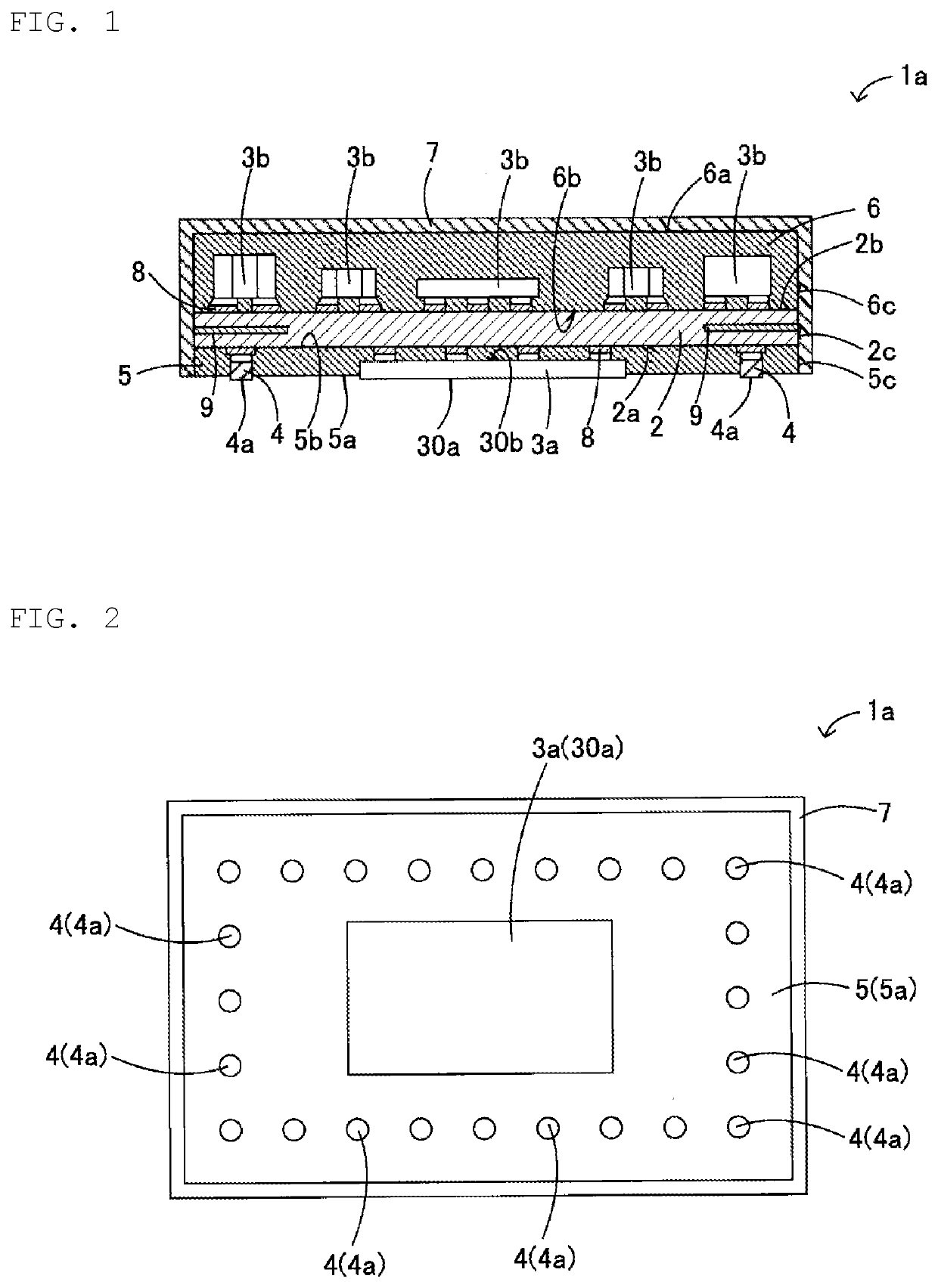
[0028]A radio-frequency module 1a according to a first embodiment of the present disclosure will be described with reference to FIGS. 1 and 2. Note that FIG. 1 is a sectional view of the radio-frequency module 1a, and FIG. 2 is a plan view illustrating a lower surface 5a of a first sealing resin layer 5 of the radio-frequency module 1a.

[0029]As illustrated in FIGS. 1 and 2, the radio-frequency module 1a according to this embodiment includes a wiring board 2, a first component 3a and a plurality of connection terminals 4 mounted on a lower surface 2a of the wiring board 2, a first sealing resin layer 5 sealing the first component 3a and the connection terminals 4, a plurality of second components 3b mounted on an upper surface 2b of the wiring board 2, a second sealing resin layer 6 sealing the second components 3b, and a shield film 7 covering side surfaces 5c of the first sealing resin layer 5 and side surfaces 6c and an upper surface 6a of the second sealing resin layer 6, and si...

second embodiment

[0052]A radio-frequency module 1b according to a second embodiment of the present disclosure will be described with reference to FIGS. 6 and 7. Note that FIG. 6 is a sectional view of the radio-frequency module 1b, and FIG. 7 is a plan view illustrating a lower surface 5a of a first sealing resin layer 5 of the radio-frequency module 1b.

[0053]The radio-frequency module 1b according to this embodiment differs from the radio-frequency module 1a of the first embodiment described with reference to FIGS. 1 and 2 in that, as illustrated in FIGS. 6 and 7, a plurality of first components 3a are mounted on a lower surface 2a of a wiring board 2 and connection terminals 4 are arranged between the adjacent first components 3a.

[0054]The configuration other than the above is identical to that of the radio-frequency module 1a of the first embodiment, and therefore, the description thereof will be omitted by giving identical symbols.

[0055]In this embodiment, the two first components 3a are mount...

third embodiment

[0057]FIGS. 8A and 8B are a sectional view and a plan view of a radio-frequency module according to a third embodiment of the present disclosure, respectively. The third embodiment differs from the first embodiment described with reference to FIGS. 1 and 2 in that connection terminals 4 are formed of bumps such as solder bumps or Au bumps, and can provide similar effects as in the first embodiment.

[0058]Note that the present disclosure is not limited to the above-described embodiments, and various modifications other than those described above can be made without departing from the spirit of the disclosure. For example, the configurations of the above-described embodiments and modifications may be combined.

[0059]For example, a second component 3b and another component may be mounted on a lower surface 2a of a wiring board 2. At this time, it is desirable that the height of the second component 3b or the other component mounted on the lower surface 2a of the wiring board 2 is prefera...


PUM


Abstract

A radio-frequency module 1a includes a wiring board 2, a first component 3a mounted on a lower surface 2a of the wiring board 2, a plurality of connection terminals 4, a first sealing resin layer 5 that covers the first component 3a and the connection terminals 4, a plurality of second components 3b mounted on an upper surface 2b of the wiring board 2, a second sealing resin layer 6 that covers the second components 3b, and a shield film 7. By adjusting surface roughness of a lower surface 5a of the first sealing resin layer 5, surface roughness of a lower surface 30a of the first component 3a, and surface roughness of a lower surface 4a of the connection terminal 4, it is possible to prevent abnormal deposition of plating and a crack in the first component 3a, and to prevent malfunction of the radio-frequency module 1a.

Description

[0001]This is a continuation of International Application No. PCT / JP2019 / 010730 filed on Mar. 15, 2019 which claims priority from Japanese Patent Application No. 2018-052323 filed on Mar. 20, 2018. The contents of these applications are incorporated herein by reference in their entireties.BACKGROUND OF THE DISCLOSUREField of the Disclosure[0002]The present disclosure relates to a radio-frequency module in which a component is mounted on one main surface of a wiring board and the component is covered with a sealing resin layer.Description of the Related Art[0003]Conventionally, a radio-frequency module such as a module 100 illustrated in FIG. 9 is proposed. In the module 100, a plurality of components 102 sealed with a first sealing resin layer 103 is mounted on an upper surface 101a of a wiring board 101, and a semiconductor component 104 and connection terminals 105 sealed with a second sealing resin layer 106 are mounted on a lower surface 101b of the wiring board 101. In such a m...

Claims


Application Information

Patent Timeline
Patent Type & Authority Applications(United States)
IPC IPC(8): H01L23/31H01L23/552H01L25/065H01L25/16H01L21/56H01L23/498
CPCH01L23/3185H01L23/49811H01L21/56H01L21/561H01L25/0652H01L25/165H01L23/552H01L2924/181H01L2924/19105H01L2924/3025H01L2224/97H01L2924/18161H01L23/3121H01L23/562H01L23/49805H01L23/49816H01L2224/16227H01L25/0657H01L25/16H01L2225/06517H01L2225/06572H01L2924/15311H01L2924/00012H01L2224/81
Inventor NOMURA, TADASHIKUSUYAMA, TAKAFUMIECHIKAWA, YOSHITAKA
Owner MURATA MFG CO LTD
Why Eureka
Try Eureka