
Method of calibrating a mobile manipulator

a mobile manipulator and mobile technology, applied in the field of robot manipulators, can solve the problems of high cost, unsafe robot manipulators, and tedious manual calibration upon installation

Inactive Publication Date: 2020-12-24
THE GOVERNINIG COUNCIL OF THE UNIV OF TORANTO
View PDF0 Cites 2 Cited by
  • Summary
  • Abstract
  • Description
  • Claims
  • Application Information

AI Technical Summary

Benefits of technology

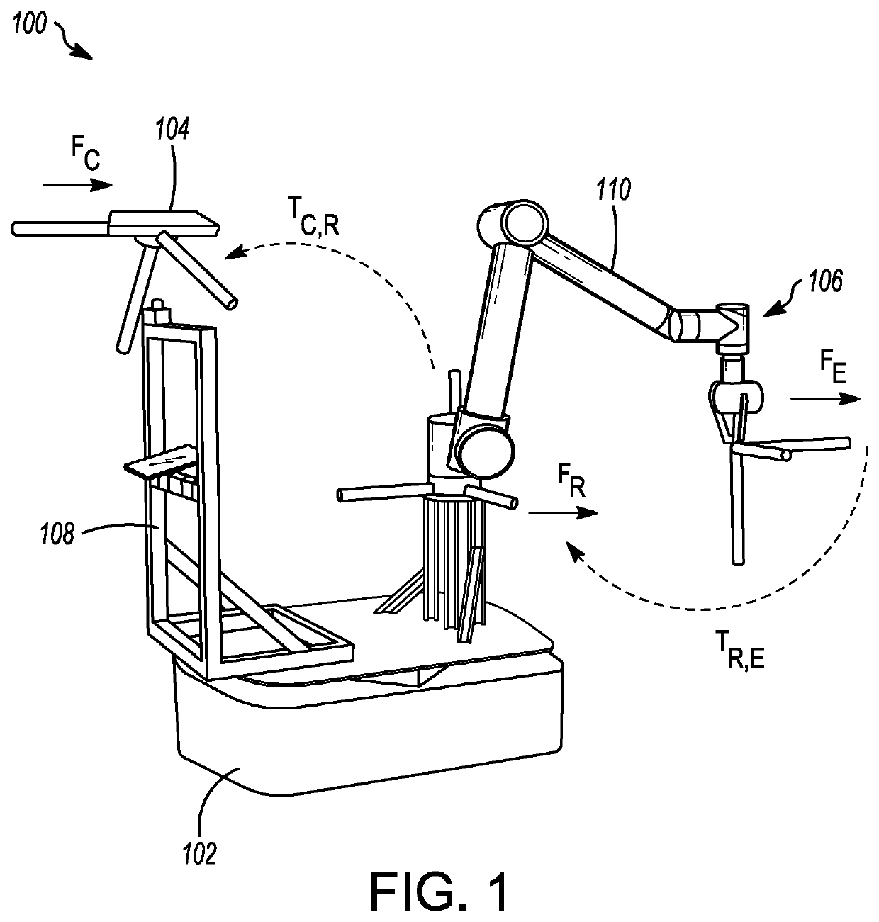
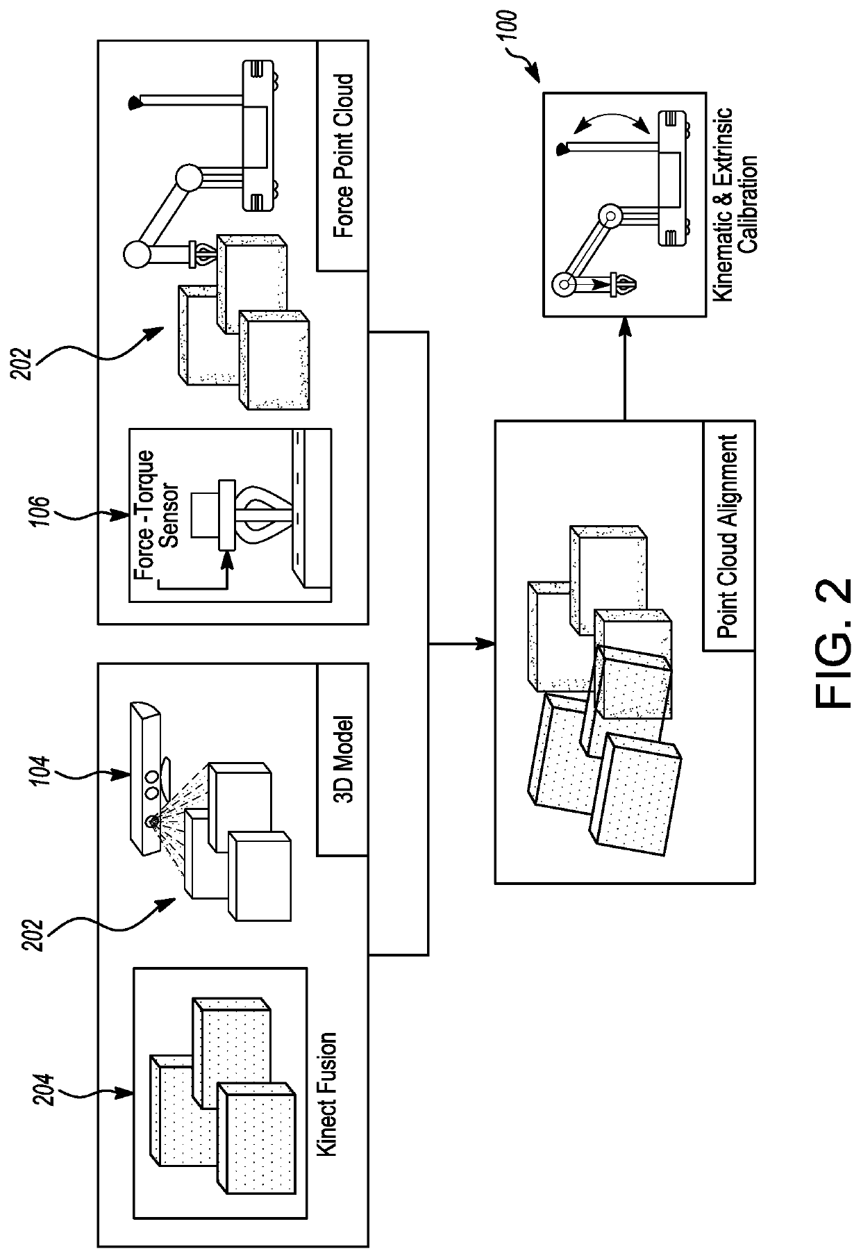
The patent describes a method for calibrating a manipulator and an external sensor. The method involves generating two point cloud maps: one using depth information and one using contact information. These maps are then aligned to recover extrinsic parameters. The depth sensor is stationary relative to the base frame of the mobile manipulator and can collect depth information from a single or multiple vantage points. The method also accounts for kinematic model biases of the manipulator. The technical effect of this patent is to provide a reliable and accurate method for calibrating a manipulator and external sensor, which can be used in various applications such as industrial automation and robotics.

Problems solved by technology

Currently, person-safe robot manipulators, be it fixed-base units or mobile, and the vision sensors upon which they rely, require tedious manual calibration upon installation.
Manual calibration and / or calibration carried out in a pre-specified calibration area are known to enable accurate operation; however, they come at a significant cost.
These options require additional personnel, equipment, and time.
Hence, they are costlier overall, and decrease the flexibility of the robotic systems.
Further, most calibration parameters may change over a robot's lifetime.
Such change, as an example, may be due to general wear and tear.
Despite the success of self-calibration for sensing applications, there has been relatively little work on combined sensor-actuator self-calibration for mobile platforms.
However, the use of supplementary equipment, often not readily available, makes these approaches less attractive than self-calibration.
Unfortunately, these methods do not apply to a fixed camera.
However, the drawback is that the end-effector needs to remain in the field of view of the camera at all times.
However, such high accuracy may not be essential in collaborative, person-safe platforms, where target tasks are typically grasping of objects.

Method used


Image

  • Method of calibrating a mobile manipulator
  • Method of calibrating a mobile manipulator
  • Method of calibrating a mobile manipulator

Examples


Embodiment Construction

[0039]The present disclosure relates to a method of automatic, in-situ calibration of a (an optionally mobile) manipulator end-effector to an externally-mounted depth sensor, using only the on-board hardware.

[0040]The following description illustrates principles, which may be applied in various ways to provide many different alternative embodiments. This description is not meant to limit the inventive concepts in the appended claims. The principles, structures, elements, techniques, and methods disclosed herein may be adapted for use in other situations where calibration of relative position and orientation of a sensor mounted on a system to an end-effector of the mobile system is desired, wherein the position of the sensor is unaffected by the movement of the end-effector. The system may be mobile or stationary.

[0041]While exemplary embodiments of the present technology have been shown and described in detail below, it will be clear to the person skilled in the art that changes, an...


PUM


Abstract

A method is provided for calibrating a manipulator and an external sensor. The method includes generating a first cloud map using depth information collected using a depth sensor, and generating a second cloud map using contact information collected using a contact sensor, which is coupled to an end effector of the manipulator. Thereafter, the first cloud map and the second cloud map are aligned to recover extrinsic parameters using the iterative closest point algorithm. The depth sensor is stationary relative to a base frame of the manipulator, and the depth information corresponding to a rigid structure is collected by capturing depth information from multiple vantage points by navigating the manipulator. The contact information is collected by moving an end effector of the manipulator over the rigid structure.

Description

FIELD OF THE INVENTION[0001]In general, the subject matter disclosed herein relates to robot manipulators. More particularly, but not exclusively, the subject matter relates to calibration of relative position and orientation of an external sensor to the base and end-effector of the robot manipulator.BACKGROUND[0002]Collaborative mobile manipulators have the potential to become ubiquitous outside of factory environments, if certain challenges are addressed. One among those challenges corresponds to calibration. Calibration, depending on the platform, may involve determining intrinsic (e.g., camera focal length) and extrinsic (i.e., relative pose) sensor parameters, as well as kinematic parameters of the manipulator arm (e.g., joint biases and link length offsets).[0003]Currently, person-safe robot manipulators, be it fixed-base units or mobile, and the vision sensors upon which they rely, require tedious manual calibration upon installation. This is necessary to ensure that such a m...

Claims


Application Information

Patent Timeline
IPC IPC(8): B25J9/16B25J9/04B25J13/08B25J19/02
CPCB25J9/162B25J9/1692B25J19/023B25J9/046B25J13/085B25J5/007
Inventor KELLY, JONATHAN SCOTTLIMOYO, OLIVERABLETT, TREVOR
Owner THE GOVERNINIG COUNCIL OF THE UNIV OF TORANTO
Learn More