Supplemental energy generation and storage for trains

Pending Publication Date: 2020-12-24
ECOLUTION KWH LLC
View PDF0 Cites 1 Cited by
  • Summary
  • Abstract
  • Description
  • Claims
  • Application Information

AI Technical Summary

Benefits of technology

The patent describes a way to keep generators in place within a train car. A support frame is used to hold the generators in place. This frame consists of two shafts that are connected between the sides of the train car. A cross frame member is attached to these shafts and runs parallel to the brakes. This frame has holes in it so that the axles can pass through and rotate freely. The generators are attached to the frame using bracket members, allowing them to be easily connected and disconnected. This design helps keep the generators secure and easy to maintain.

Problems solved by technology

Despite all this, railway companies still face difficulties and obstacles in being successful.
Among other things, as the rails are privately owned by the rail companies, the costs to maintain them can be substantial.
There are also significant costs in maintenance of equipment.
As a result, there are often very low, if any, profit margins and many passenger carrying train systems and companies are highly subsidized and struggle to economically compete with other forms of personal transportation.

Method used


Image

  • Supplemental energy generation and storage for trains
  • Supplemental energy generation and storage for trains
  • Supplemental energy generation and storage for trains

Examples


Embodiment Construction

[0040]While the present invention is susceptible of embodiment in many different forms, there is shown in the drawings and will herein be described in detail specific embodiments, with the understanding that the present disclosure is intended as an exemplification of the principles of the present invention and is not intended to limit the invention to the embodiment disclosed.

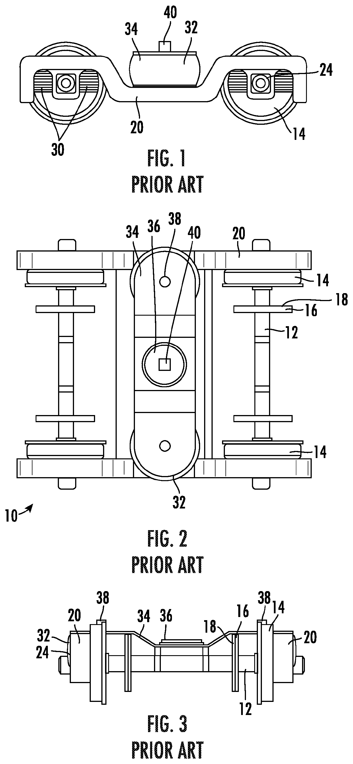
[0041]Referring to FIGS. 1 through 3, basic components from a train bogie 10 as presently embodied in the prior art are shown in connection with a pair of axles 12 each with a pair of wheels 14 for engaging the rail (not shown). On each axle 12 are a pair of discs 18 that allow disc brake rotors 16 to be attached thereto for stopping or slowing the train when calipers are engaged. The bogie 10 itself comprises a pair of side frame members 20 that are connected together by a bogie transom 22. The axles 12 are rotationally connected relative to the bogie side frame members 20 through axles boxes 24.

[0042]A pair o...


PUM


Abstract

The invention relates to the supplemental generation of energy from operation of a train, and specifically to the generation of energy in connection to the rotation of disc brake rotors in combination with generators. Rotation of the disc brake rotors creates rotational energy that is transmitted to the generators, which then transmits the energy to a series of batteries for storage. The batteries may be stored in the platform for the train and / or within the train car itself. Energy from the batteries may be utilized by removal of the batteries from the train or through a number of outlets, sockets or connectors associated with the train car or platform.

Description

[0001]This application is a continuation-in-part of pending U.S. non-provisional patent application Ser. No. 16 / 871,281, filed on May 11, 2020, which is a continuation of U.S. non-provisional patent application Ser. No. 15 / 858,848, filed on Dec. 29, 2017, and which issued on Jun. 2, 2020 as U.S. Pat. No. 10,668,814, which claims benefit to U.S. provisional patent application Ser. No. 62 / 440,775, filed on Dec. 30, 2016, the disclosures of which are herein incorporated by reference in their entireties. This application also claims benefit to U.S. provisional patent application No. 63 / 024,888 filed on May 14, 2020, the disclosure of which is herein incorporated by reference in its entirety. This application is also a continuation-in-part of pending U.S. non-provisional patent application Ser. No. 16 / 876,010, filed on May 16, 2020, which is a continuation of abandoned U.S. non-provisional patent application Ser. No. 16 / 726,862 filed on Dec. 25, 2019, which claims benefit to U.S. provisi...

Claims


Application Information

Patent Timeline
IPC IPC(8): B60L7/10F16D55/226H02K7/102
CPCF16D55/226B60L2220/44B60L7/10H02K7/102H02K16/00H02K7/106H02K7/1846B60L2200/26B60L15/007Y02T10/64
Inventor THEN-GAUTIER, JOHNNYMEDINA THEN, JOHANNE G.
Owner ECOLUTION KWH LLC
Why Eureka
Try Eureka