Retractable mixing device and method

a technology of mixing device and fluid, which is applied in the direction of mixer, mixer accessories, mixing, etc., can solve the problems of settling that is not of any consequence or even desirable, damage to the tank, and may be detrimental to the fluid, so as to facilitate longitudinal sliding of the shaft, facilitate rotation of the shaft, and facilitate the effect of volum

Inactive Publication Date: 2015-01-15
SPX FLOW INC
View PDF1 Cites 0 Cited by
  • Summary
  • Abstract
  • Description
  • Claims
  • Application Information

AI Technical Summary

Benefits of technology

[0010]Another embodiment of the present invention relates to a mixer assembly. The mixer assembly includes an impeller, a motor to rotate the impeller, and a shaft affixed to the impeller and convey torque from the motor to the impeller. The mixer assembly additionally includes housing having sufficient volume to contain the impeller, a seal, and an actuator. The seal is disposed in the housing. The seal is configured to facilitate rotation of the shaft and being configured to facilitate longitudinal sliding the shaft while reducing leakage of a fluid across the seal. The actuator is configured to urge the shaft to move longitudinally. The impeller is drawn into the housing in response to the actuator moving the shaft.

Problems solved by technology

Settling of some fluid may be of no consequence or even desirable.
However, in other fluid, settling may be detrimental.
For example, in petroleum product, settling may cause basic components to precipitate or concentrate at or near the bottom of the tank—damaging the tank and reducing the quality of the petroleum product stored therein.
Since this type of storage vessel is typically very large diameter with relatively short height, top entry agitators are generally not practical and side entry agitators are used.
There is currently no provision to extract the shaft and impeller from the tank without breaking the vessel seal which could result in a substantial spillage from the vessel.

Method used


Image

  • Retractable mixing device and method
  • Retractable mixing device and method
  • Retractable mixing device and method

Examples


Embodiment Construction

[0029]The present invention provides a retractable impeller for a tank mixing system and method of retracting an impeller from a tank. For the purposes of this disclosure, the term “tank” and variations thereof refer to a container or vessel of any suitable size or shape and to contain any suitable fluid. In a particular example, the tank or tanks described herein may be suitable for containing many tens, hundreds, thousands, millions etc. of liters of fluid. In a specific example, the fluid may be a petroleum product stored in a tank having a relatively large volume such as, hundreds to millions of barrels.

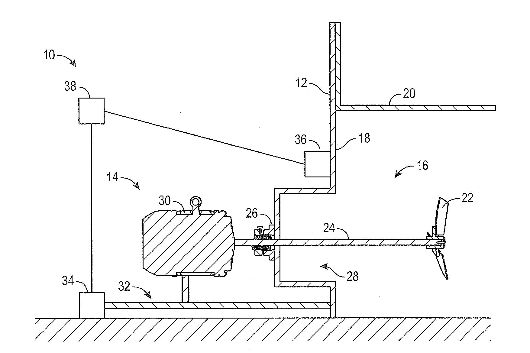
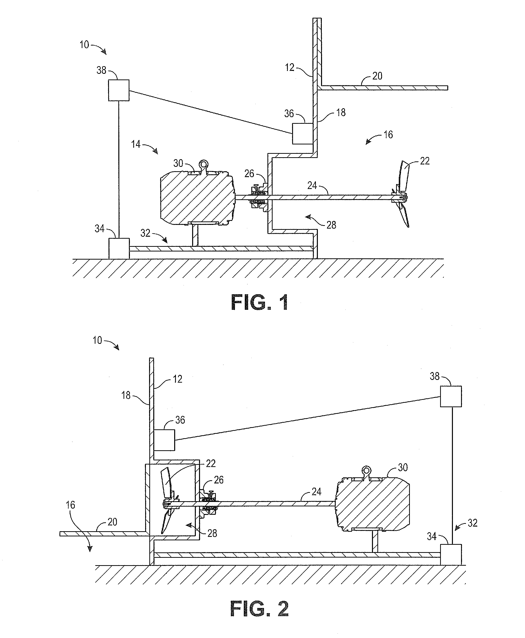
[0030]FIG. 1 is a simplified cross sectional view of a tank mixing system 10 in a first conformation according to an embodiment of the invention. As shown in FIG. 1, the tank mixing system 10 includes a tank 12 and impeller assembly 14. The tank 12 is configured to contain a suitable fluid 16. Suitable examples of the fluid 16 include petroleum based fluid such as oil and fuel an...


PUM


Abstract

A system for mixing a fluid in a tank includes a mixer assembly, a housing, and an actuator. The mixer assembly has a motor, a shaft, and an impeller. The housing is disposed in a side wall of the tank. The housing has sufficient volume to contain the impeller. The actuator is configured to retract the mixer assembly and draw the impeller into the housing. The mixer assembly has a first conformation and a second conformation. In the first conformation the impeller is disposed in a main portion of the tank and configured to mix the fluid in response to rotation of the impeller via the motor and shaft. In the second conformation the impeller is disposed in the housing and out of the main portion of the tank.

Description

CROSS-REFERENCE TO RELATED APPLICATIONS[0001]This application claims priority to U.S. provisional application entitled, RETRACTABLE MIXING DEVICE AND METHOD, filed Jul. 15, 2013, having Ser. No. 61 / 846,264, the disclosure of which in hereby incorporated by reference in its entirety.FIELD OF THE INVENTION[0002]The present invention generally relates to a mixing device and method. More particularly, the present invention pertains to a device and method for mixing a fluid disposed in a tank.BACKGROUND OF THE INVENTION[0003]It is generally known that fluids stored in tanks will often settle. Settling of some fluid may be of no consequence or even desirable. However, in other fluid, settling may be detrimental. For example, in petroleum product, settling may cause basic components to precipitate or concentrate at or near the bottom of the tank—damaging the tank and reducing the quality of the petroleum product stored therein. In general, this problem is referred to as basic sediment and ...

Claims


Application Information

Patent Timeline
Patent Type & Authority Applications(United States)
IPC IPC(8): B01F7/00B01F27/71
CPCB01F7/00233B01F27/2312B01F27/71B01F27/05B01F27/11
Inventor CREATHORN, ANDREWGIGAS, BERNDMCCARROLL, MICHAEL
Owner SPX FLOW INC
Why Eureka
Try Eureka