
Fuel cell system

Active Publication Date: 2020-12-24
TOYOTA JIDOSHA KK
View PDF0 Cites 1 Cited by
  • Summary
  • Abstract
  • Description
  • Claims
  • Application Information

AI Technical Summary

Benefits of technology

The patent text discusses a fuel cell system that can identify and cancel out fuel deficiencies in individual cells to prevent performance degradation. However, this can result in higher manufacturing costs due to the need for a voltage detector for each cell. The patent aims to address this issue and provide a cost-effective solution to prevent output performance issues.

Problems solved by technology

The manufacturing cost of the voltage detector is higher as it detects voltage of unit cells for each set of a smaller number of unit cells, and the manufacturing cost is higher when the voltage of the unit cells is detected for each unit cell, as compared with the case where the voltage is detected for every two or more unit cells, or only the voltage of the whole fuel cell is detected.
Also, in the fuel cell system having a plurality of fuel cells, if a voltage detector having a high manufacturing cost is connected to each of the fuel cells, the manufacturing cost of the fuel cell system will be increased.

Method used


Image

  • Fuel cell system
  • Fuel cell system
  • Fuel cell system

Examples


third modified example

of Fuel Deficiency Cancellation Control

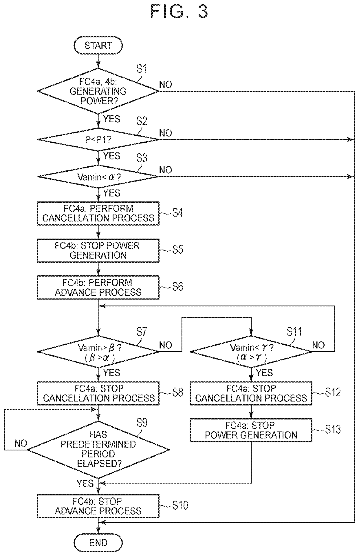
[0087]FIG. 6 is a flowchart showing a third modified example of fuel deficiency cancellation control. The ECU 3 determines whether requests for start of power generation are generated to the FC 4a and the FC 4b (step S1a). The case where the requests for start of power generation are generated to both of the FC 4a and the FC 4b is, more specifically, the case where requests for start of power generation are generated to both of the FC 4a and the FC 4b, in a condition where power generation is stopped in both of the FC 4a and the FC 4b. For example, power generation is stopped in the FC 4a and the FC 4b immediately after the ignition switch 7 is switched from OFF to ON, and the FC 4a and the FC 4b are requested to start generating electric power. Also, in a system in which power generation of both of the FC 4a and the FC 4b are temporarily stopped when the vehicle is temporarily stopped, when the accelerator pedal is operated in this condition, ...

first modified example

of Voltage Sensors

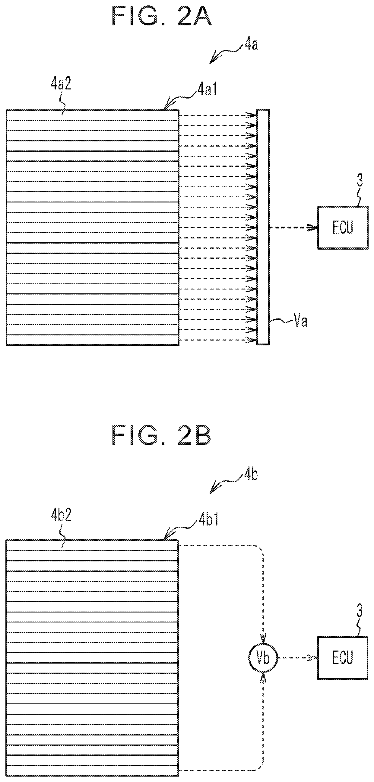
[0098]FIG. 7A and FIG. 7B show a first modified example of voltage sensors. FIG. 7A shows a part of a voltage sensor Vaa, and FIG. 7B shows a part of a voltage sensor Vba. The voltage sensor Vaa detects a voltage for every two unit cells, with respect to all unit cells 4a2 of the FC 4a. Namely, the number of detection channels of the voltage sensor Vaa is one half of the total number of the stacked unit cells 4a2. On the other hand, the voltage sensor Vba detects a voltage for every four unit cells, with respect to all unit cells 4b2 of the FC 4b. Accordingly, the number of detection channels of the voltage sensor Vba is one-fourth of the total number of the stacked unit cells 4b2. In this case, too, the number of detection channels of the voltage sensor Vba is smaller than that of the voltage sensor Vaa, and thus, the manufacturing cost of the voltage sensor Vba is lower than that of the voltage sensor Vaa. Accordingly, the manufacturing cost is reduced, as compar...

second modified example

of Voltage Sensors

[0101]FIG. 8A and FIG. 8B show a second modified example of voltage sensors. A voltage sensor Vab detects a voltage for each unit cell, with respect to a part of the unit cells 4a2, and detects a voltage for every two unit cells, with respect to another part of the unit cells 4a2. A voltage sensor Vbb detects a voltage for every two unit cells, with respect to a part of the unit cells 4b2, and detects a voltage for every four unit cells, with respect to another part of the unit cells 4b2. In this case too, the voltage sensor Vab may detect a voltage of the unit cells 4a2 for every “N” unit cells on average over the whole FC 4a, and the voltage sensor Vbb may detect a voltage of the whole FC 4b, or a voltage of the unit cells 4b2 for every “M” unit cells on average over the whole FC 4b, where “M” is larger than “N”. In this case, the manufacturing cost of the voltage sensor Vbb is lower than that of the voltage sensor Vab.

[0102]In the above case, in steps S3, S7, an...


PUM


Abstract

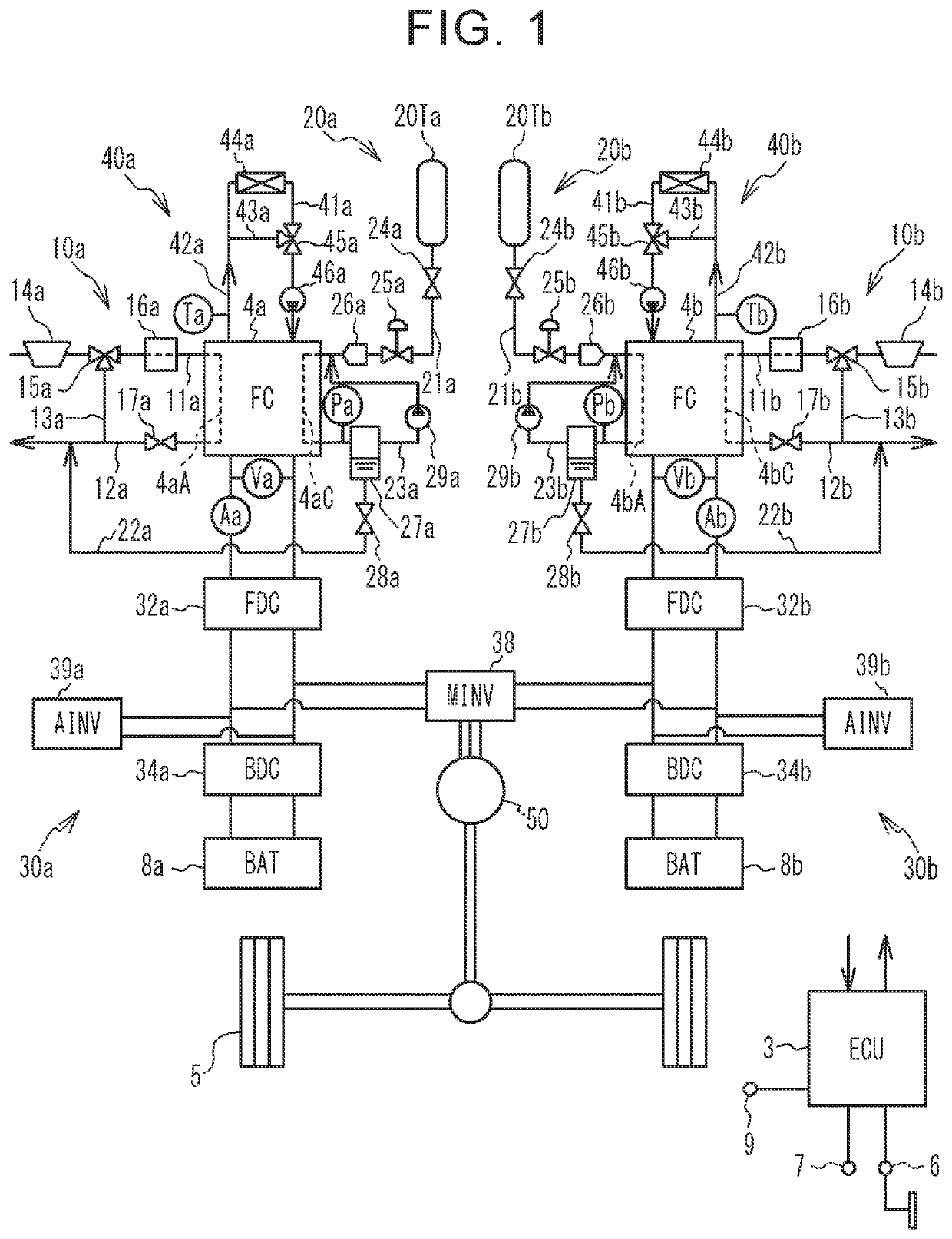
A fuel cell system includes a first fuel cell having first unit cells stacked together, a second fuel cell having second unit cells stacked together, a first voltage detector, a second voltage detector, and a controller. The first voltage detector detects voltage of the first unit cells for every “N” unit cells on average, and the second voltage detector detects voltage of the whole second fuel cell, or detects voltage of the second unit cells for every “M” unit cells on average. The controller determines whether any of the first unit cells is in a fuel deficiency state, by referring to a detection result of the first voltage detector, and performs a cancellation process to cancel the fuel deficiency state, on the first fuel cell that is in a power generating state, while stopping power generation of the second fuel cell, when an affirmative decision is obtained.

Description

INCORPORATION BY REFERENCE[0001]The disclosure of Japanese Patent Application No. 2019-113178 filed on Jun. 18, 2019 including the specification, drawings and abstract is incorporated herein by reference in its entirety.BACKGROUND1. Technical Field[0002]The disclosure relates to a fuel cell system.2. Description of Related Art[0003]In a fuel cell having a plurality of unit cells stacked together, when fuel gas is not sufficiently supplied to a part of the unit cells, and each unit cell in this part is placed in a fuel deficiency state, the voltage of the unit cell may be reduced down to a negative voltage, and the output performance of the unit cell may deteriorate (see, for example, Japanese Unexamined Patent Application Publication No. 2006-049259 (JP 2006-049259 A)).SUMMARY[0004]In order to curb deterioration of the output performance, it may be considered to determine whether any of the unit cells is in a fuel deficiency state, and perform a cancellation process for cancelling t...

Claims


Application Information

Patent Timeline
IPC IPC(8): H01M8/04664H01M8/04537H01M8/249H01M8/04955H01M8/04303H01M8/04828H01M8/04302H01M8/0432
CPCH01M8/04302H01M8/04955H01M8/04365H01M8/04559H01M8/04552H01M8/0494H01M2250/20H01M8/249H01M8/04303H01M8/04671H01M8/04679H01M2008/1095H01M8/2457H01M8/043H01M8/0432Y02T90/40
Inventor ITOU, MASAYUKIARAKI, YASUSHI
Owner TOYOTA JIDOSHA KK
Learn More