Valve group charging device and valve group charging control method

A charging control method and technology of a charging device, which are applied in the direction of circuit devices, battery circuit devices, battery disconnection circuits, etc., can solve the problem of high charging costs, and achieve the effects of reducing charging costs and reducing output capacity

Active Publication Date: 2021-10-08
GUANGZHOU POWER SUPPLY BUREAU GUANGDONG POWER GRID CO LTD
View PDF7 Cites 0 Cited by
  • Summary
  • Abstract
  • Description
  • Claims
  • Application Information

AI Technical Summary

Problems solved by technology

[0004] Based on this, it is necessary to provide a valve group charging device and a valve group charging control method for the problem of high charging cost of the multi-valve group test platform

Method used


Image

  • Valve group charging device and valve group charging control method
  • Valve group charging device and valve group charging control method
  • Valve group charging device and valve group charging control method

Examples


Embodiment Construction

[0039] In order to make the object, technical solution and advantages of the present invention clearer, the present invention will be further described in detail below in conjunction with the accompanying drawings and embodiments. It should be understood that the specific embodiments described here are only used to explain the present invention, not to limit the present invention.

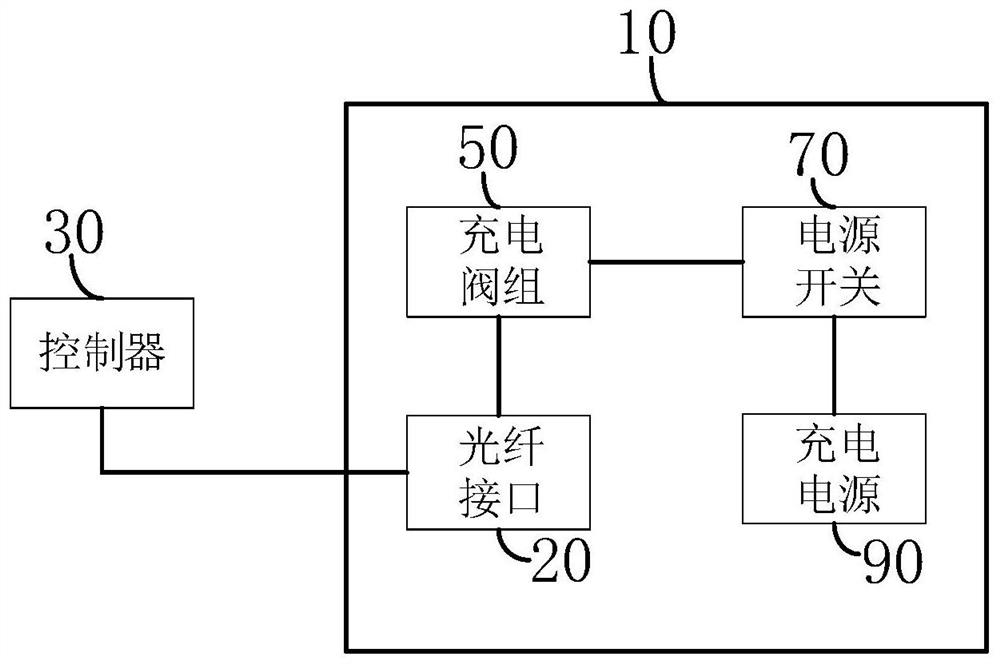
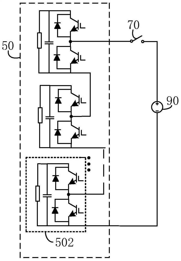
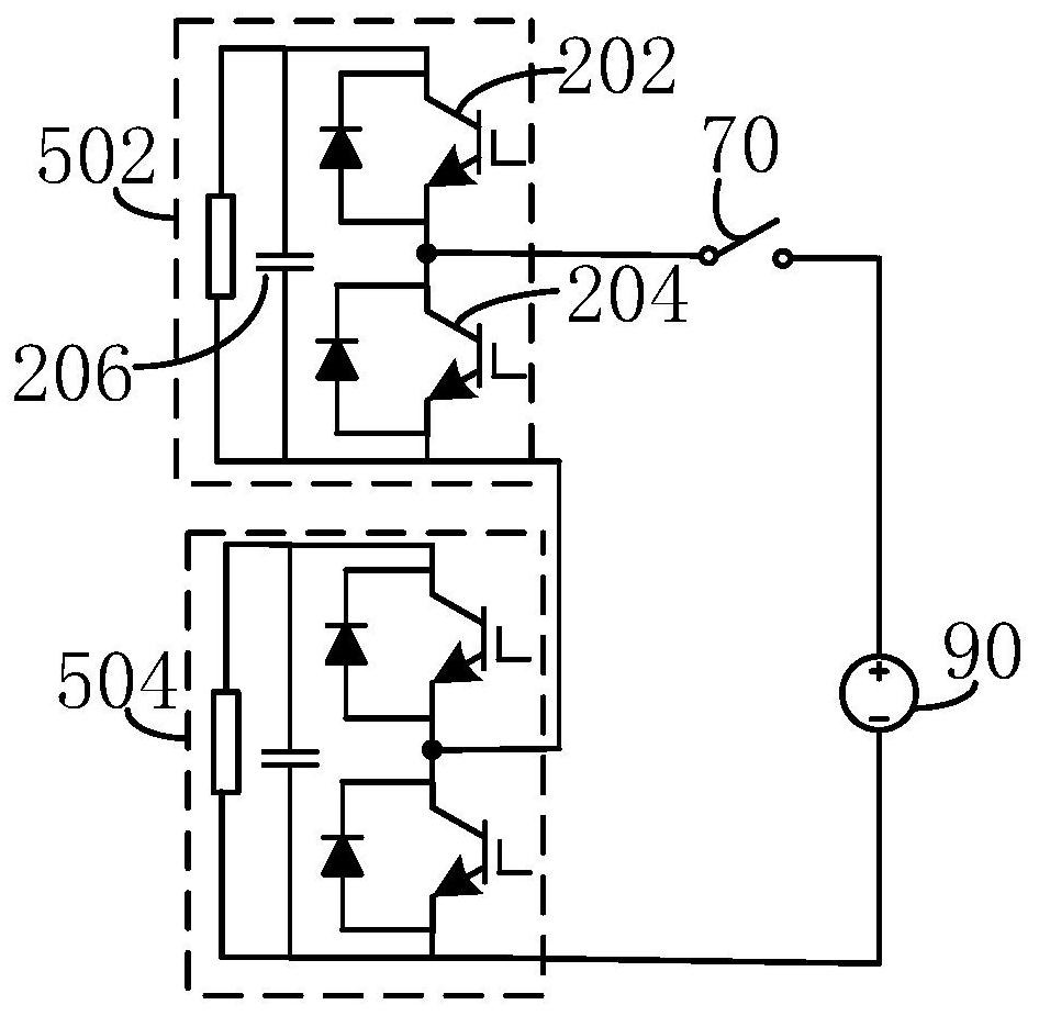
[0040] figure 1 It is a schematic structural diagram of a valve group charging device in an embodiment. Such as figure 1 As shown, a valve group charging device includes a printed circuit board 10 , a controller 30 , a valve group 50 to be charged, a power switch 70 and a charging power source 90 .

[0041] The valve group 50 to be charged, the power switch 70 and the charging power source 90 are arranged on the printed circuit board 10 , and the optical fiber interface 102 is arranged on the printed circuit board 10 .

[0042] Among them, the printed circuit board 10 is a provider of electrical...


PUM


Abstract

The invention relates to a valve group charging device and a valve group charging control method. The device includes a printed circuit board, a controller, a valve group to be charged, a power switch and a charging power supply. The valve group to be charged, the power switch and the charging power supply are arranged on a printed circuit board On the circuit board, the printed circuit board is provided with an optical fiber interface. The valve group to be charged includes at least two charging sub-modules connected in parallel or in series. Each charging sub-module is provided with a charging circuit. The controller communicates with multiple charging sub-modules through the optical fiber interface. Communication is used to send charging control signals to each charging sub-module in turn, and the charging sub-module starts the corresponding charging circuit in response to the charging control signal. The above-mentioned valve group charging device and valve group charging control method can alternately charge each sub-module without At the same time, all the sub-modules are charged at one time, so a higher charging voltage is not required, the required output capability of the charging power source is reduced, and the charging cost is reduced.

Description

technical field [0001] The invention relates to the technical field of power electronics, in particular to a valve group charging device and a valve group charging control method. Background technique [0002] The modular multilevel converter is composed of multiple sub-modules with the same structure cascaded. Among them, the valve group is the main component of the modular multilevel voltage source converter, mainly composed of semiconductor devices that can be turned off composed of sub-modules. [0003] Since the converter station requires extremely high DC charging voltage when charging on the DC side, for a test platform with multiple valve groups, the charging power supply needs to have a high output capacity, and the cost is relatively high. Contents of the invention [0004] Based on this, it is necessary to provide a valve group charging device and a valve group charging control method to solve the problem of high charging cost of a multi-valve group test platfo...

Claims


Application Information

Patent Timeline
Patent Type & Authority Patents(China)
IPC IPC(8): H02J7/00
CPCH02J7/00H02J7/0013H02J7/0047H02J7/0031G08B21/18H02J2207/50
Inventor 熊文王莉尚慧玉赵宏伟阳曾
Owner GUANGZHOU POWER SUPPLY BUREAU GUANGDONG POWER GRID CO LTD
Why Eureka
Try Eureka