Shroud for cable hangers
Active Publication Date: 2021-01-14
COMMSCOPE TECH LLC
0 Cites 3 Cited by
AI-Extracted Technical Summary
Problems solved by technology
Passive intermodulation (PIM) is a form of signal interference which degrades the performance of electrical systems, especially communications systems.
For example, components external to the signal path but present within the electrical fields generated by the signal transmission may be coupled with the signal path and introduce undesirable nonlinearities leading ...
Abstract
The present disclosure is directed to a shroud for a cable hanger which may isolate the metal interfaces between cable hangers and their supporting structures. The present disclosure is also directed to an interference mechanism of the shroud which may minimize or eliminate accidental escape of the hanger from a supporting structure.
Application Domain
Snap-action fastenersPipe supports +1
Technology Topic
Structural engineeringClassical mechanics +1
Image
Examples
- Experimental program(1)
Example
[0032]The present invention is described with reference to the accompanying drawings, in which certain embodiments of the invention are shown. This invention may, however, be embodied in many different forms and should not be construed as limited to the embodiments that are pictured and described herein; rather, these embodiments are provided so that this disclosure will be thorough and complete and will fully convey the scope of the invention to those skilled in the art. It will also be appreciated that the embodiments disclosed herein can be combined in any way and/or combination to provide many additional embodiments.
[0033]Unless otherwise defined, all technical and scientific terms that are used in this disclosure have the same meaning as commonly understood by one of ordinary skill in the art to which this invention belongs. The terminology used in the below description is for the purpose of describing particular embodiments only and is not intended to be limiting of the invention. As used in this disclosure, the singular forms “a”, “an”, and “the” are intended to include the plural forms as well, unless the context clearly indicates otherwise. It will also be understood that when an element (e.g., a device, circuit, etc.) is referred to as being “connected” or “coupled” to another element, it can be directly connected or coupled to the other element or intervening elements may be present. In contrast, when an element is referred to as being “directly connected” or “directly coupled” to another element, there are no intervening elements present.
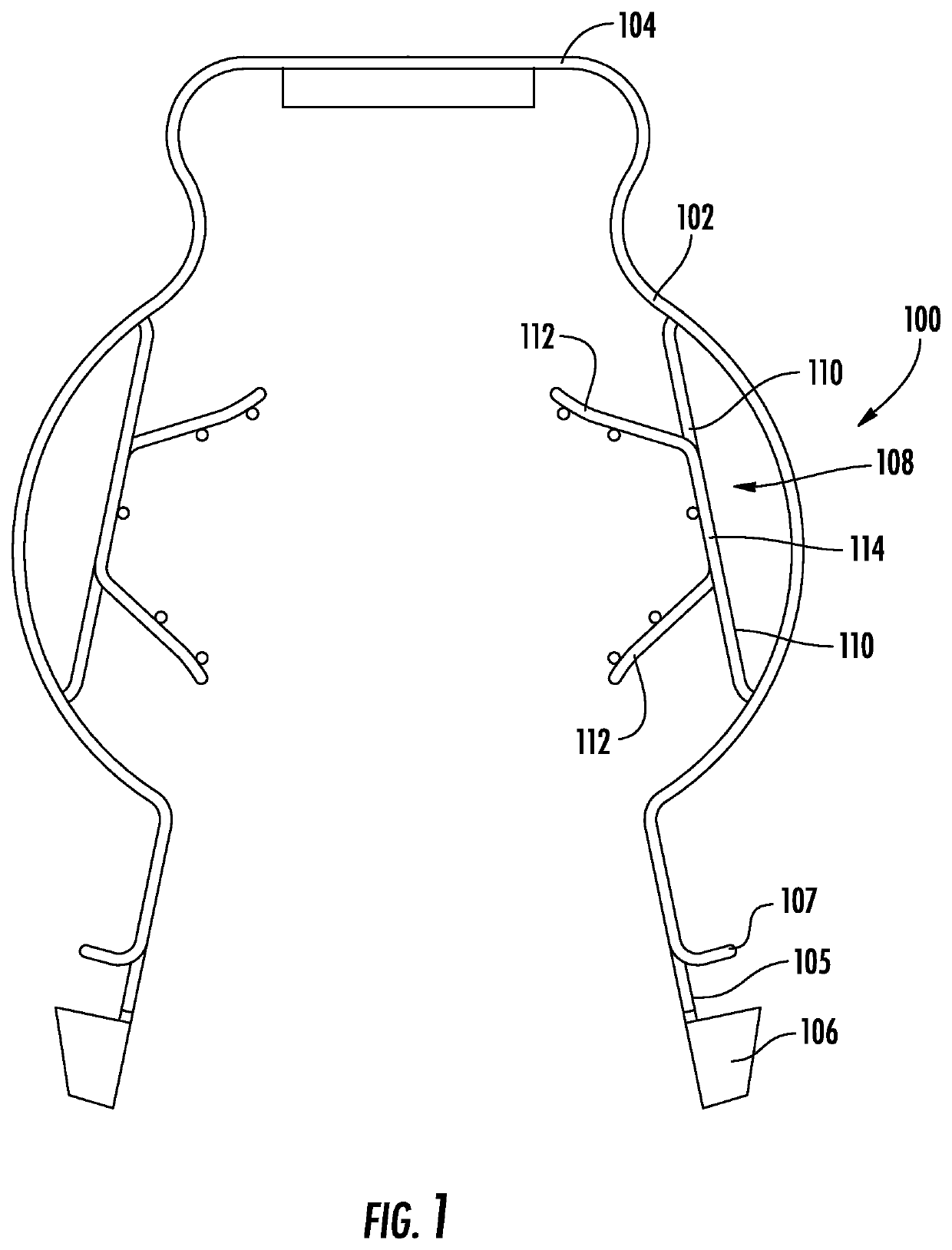
[0034]Referring now to the figures, a cable hanger, designated broadly at 100, is shown in FIG. 1. The hanger 100 includes curved arms 102 that extend from a generally flat base 104. Locking projections 106 extend from the free ends (i.e., the distal ends) of the arms 102. Locking tabs 107 may also extend from the arms 102 at positions typically spaced apart from and proximal to the locking projections 106. In some embodiments, the hanger 100 also contains a gripping mechanism 108. The gripping mechanism 108 employs two adjacent cantilevered tabs 110 extending from the interior surface of the arm 102. The cantilevered tabs 110 may terminate in grip pads 112 and may optionally be joined together by a joint 114. When cables are inserted into the hanger 100, the gripping mechanism 108 accepts the cables within the cantilevered tabs 110 and grip pads 112 to secure and center the cables within the hanger 100. Various embodiments of the gripping mechanism 108 may be provided, as discussed in U.S. Pat. No. 9,866,004 to Vaccaro, the disclosure of which is hereby incorporated herein in its entirety.
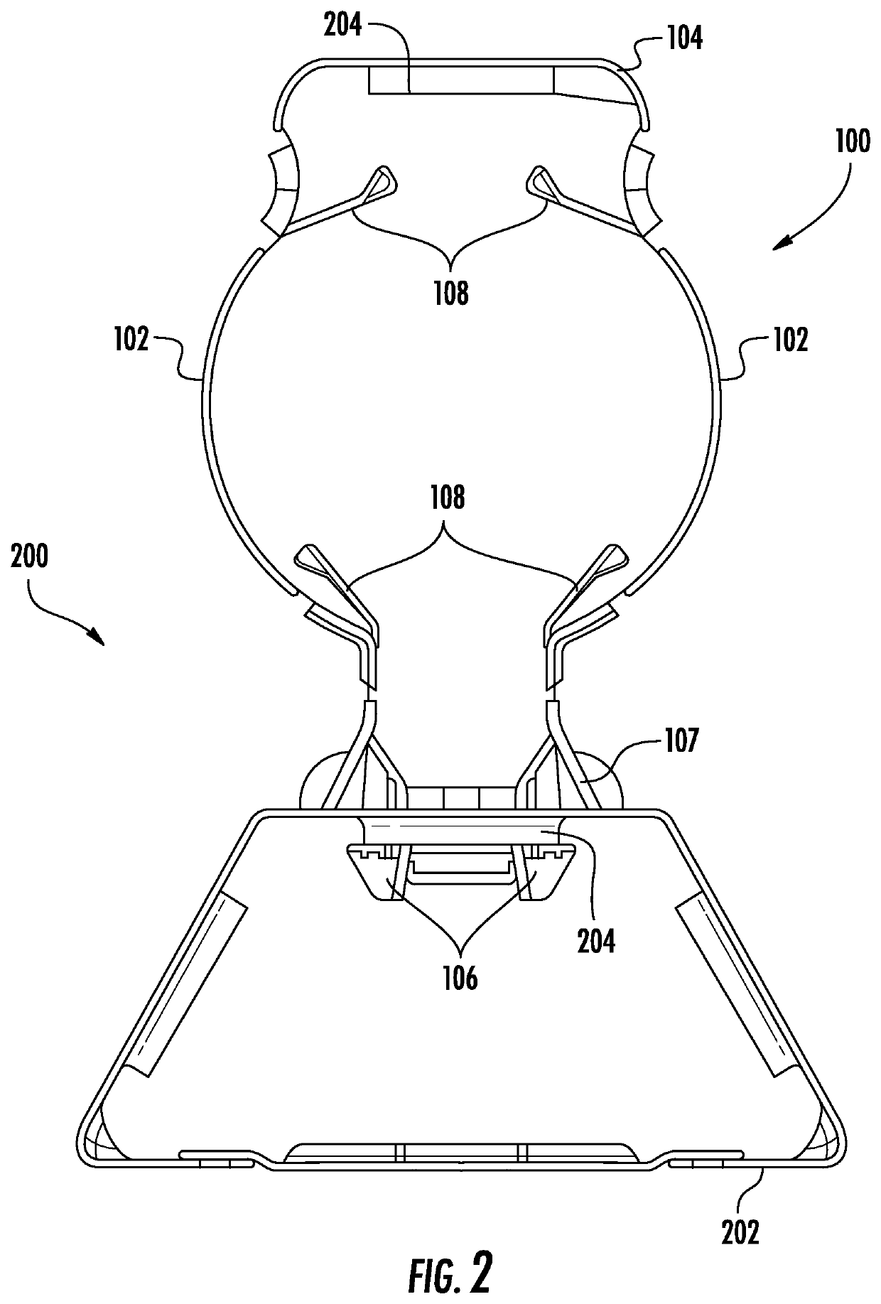
[0035]As can be seen in FIG. 2, a cable hanger installation 200 is formed when the locking projections 106 are inserted through an optionally reinforced hole or aperture 204 to mate the hanger 100 to a structure 202 (e.g., a tower structure). The base 104 of the hanger 100 may optionally include a second reinforced hole 204 that can receive the locking projections 106 of another hanger 100 to mount a second cable or group of cables. The locking tabs 107 and the locking projections 106 cooperatively form a receiving surface 105 which contacts, grips, cradles, and/or captures the reinforced hole 204, thereby forming one embodiment of a contact surface on the distal end of the arms 102. Once attached, the arms 102 together generally define a circle within which a cable can be grasped, as may be aided by a gripping mechanism 108.
[0036]Those skilled in this art will appreciate that the cable hangers 100 discussed above are typically formed of a metallic material, such as steel, and may be formed as a unitary member (often from a flat blank stamped from sheet steel and bent into a desired shape). Also, it will be apparent to those of skill in this art that the cable hangers 100 can be arranged in a “stacked” relationship by inserting the locking projections 106 of one cable hanger 100 into a mounting hole 204 in the base 104 of a second cable hanger 100 in the manner described above with respect to the solitary cable hanger 100 in FIG. 2. The second cable hanger 100 may be identical to or different from the first cable hanger 100 as needed for hanging the cable in question. Thus, as used herein, the structure 202 may refer to either a different structure (e.g., a tower) or another hanger 100.
[0037]The foregoing demonstrates one type of metal-on-metal joint in an exemplary cable hanger installation 200: the receiving surface 105, bounded by the locking tabs 107 and the locking projections 106, forms the contact surface between the hanger 100 and the structure 202. The metal-on-metal contact is susceptible to generating PIM, especially when exposed to high energy RF fields.
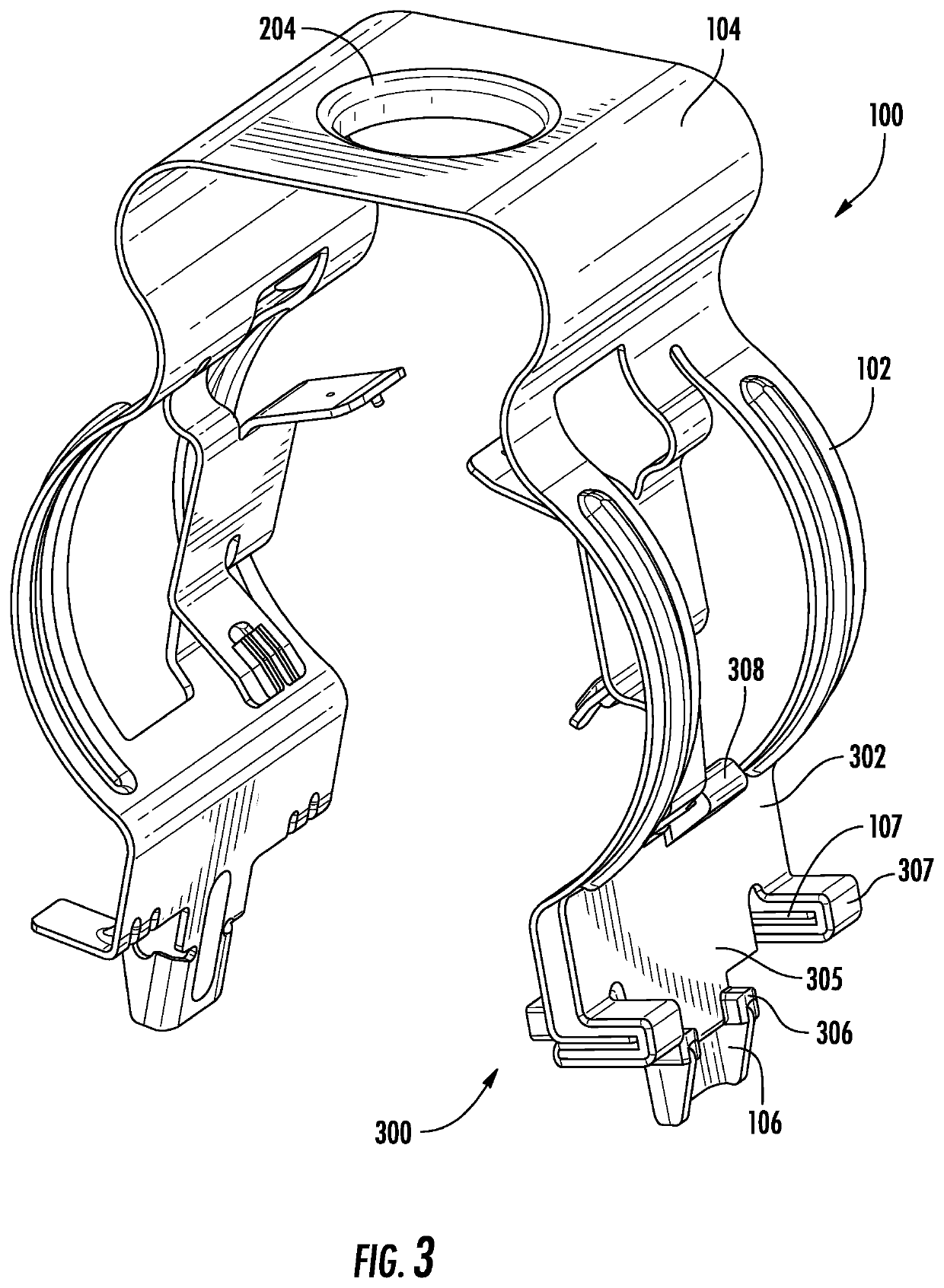
[0038]In one embodiment of the present invention, a shroud may be placed over the contact surfaces of the hanger 100 to minimize and/or eliminate metal-on-metal contact with the structure 202. For instance, FIG. 3 depicts a shroud 300 placed over a contact surface of a hanger 100. The shroud 300 has a body; the outward surface 302 of the body is visible in FIG. 3. The locking tabs 107 are enclosed in locking tab covers 307, while the locking projections 106 are covered by the locking projection covers 306. As seen in FIG. 4, the locking tabs 107 are received by an inward receiving surface 309. The locking projections 106 may optionally reside within indexing slots 310. The indexing slots 310 may serve to align the shroud 300 into the proper orientation and location for attachment to the hanger 100. A locking feature, such as a snap feature 308, may mate with the hanger 100 to secure the shroud 300 to the hanger 100, as shown in FIG. 3.
[0039]The receiving surface 105 of the hanger 100 is typically covered by the receiving surface 305 of the shroud 300, completing coverage of the contact surfaces on the distal end of one arm 102 of the hanger 100. The formation of the shroud receiving surface 305 in one embodiment is more directly pictured in FIG. 5. The lower surfaces of the locking tab covers 307 form the upper boundary of the shroud receiving surface 305 while the upper surfaces of the locking projection covers 306 form the lower boundary. Similarly, the locking tab covers 307 enclose an inward receiving surface 309 on the inward surface 303. The lower boundary of the shroud receiving surface 305, formed by the locking tab covers 307, is adjacent to the upper boundary of the shroud receiving surface 305. In one embodiment, the receiving surface which receives the locking tabs 107 from the hanger 100 (i.e., the inward receiving surface 309) and the receiving surface which covers the distal contact surfaces of the arm 102 (i.e., the outward receiving surface 305) share a boundary formed by the locking tab covers 307. In one embodiment, a similar shroud 300 may be placed on the second arm 102 of the hanger 100; if the hanger 100 were inserted into a hole 204, as in FIG. 2, the pair of shrouds 300 would isolate the hanger 100 from the structure, the shroud 300 itself providing the mating surface with the structure 202. As the shrouds 300 are typically formed with a nonmetallic material (such as a ceramic or polymeric material), at least within the shroud receiving surface 305, the shrouds 300 may minimize or even eliminate metal-on-metal contact within the installation 200 and provide electrical isolation therebetween, thereby reducing or eliminating the possibility of the generation of PIM.
[0040]Generally, the material selected for the outward receiving surface 305 will be nonmetallic, although it is contemplated that some portions of the shroud 300 might comprise metallic materials (e.g., as a filler to increase abrasion resistance or for reinforcement or spring-like functionality in localized portions, such as within the body or within the locking feature 308). In some embodiments, however, the shroud 300 will be substantially or completely formed from a nonmetallic material, such as a dielectric material. Exemplary materials for the shroud 300 include ceramics and polymeric materials, including those optionally reinforced or filled (e.g., with fibers, beads, or particles) or unfilled. In some embodiments, the shroud 300 is formed of polymeric materials such as acetal, polyethylene, polypropylene, PVC, or the like. For instance, rubber or rubberized polymers may be used to increase the security and/or grip strength of the connection between the hanger 100 and the structure 202 or to damp and/or provide isolation from structural vibrations. Where a particular dielectric effect is desired, the thickness of the shroud may be adjusted to achieve the effect (e.g., insulative or capacitive).
[0041]Although some embodiments generally conform to the geometry of the underlying hanger 100, other embodiments may depart from the geometry of the hanger 100. For instance, the locking tab covers 307 may form bifurcated inward receiving surfaces 309 on the inward surface 303, which individually cover the locking tabs 107 of the hanger 100 (as shown in FIG. 6) while having a portion of the shroud body disposed therebetween. In some embodiments, the locking tab covers 307 may form an inward receiving surface 309 running the width of the shroud 300 along its inward surface 303. Alternatively, or additionally, the locking projection covers 306 may form a contiguous shelf running along at least some portion of the shroud 300 instead of the discrete and localized covers 306. Likewise, any means of locking feature 308 may be employed, whether a snap, hook, clip, or the like; it is contemplated that chemical adhesives, including thermoplastic or thermoset adhesives, may substitute for or supplement a mechanical locking feature 308.
[0042]In some embodiments, the shroud 300 may be manufactured directly onto the hanger 100. For instance, the hanger 100 may be dipped into a thermoplastic or thermoset polymer in a molten state, after which the polymer hardens and forms a shroud 300 intimately bonded and conforming to the hanger 100. Similarly, the shroud 300 may be formed by spraying a material onto the hanger 100, or by casting or molding a material around the hanger 100. In some embodiments, the shroud 300 may cover only a portion or the entirety of the hanger 100. In other embodiments, the shroud 300 may be manufactured separately (e.g., by injection molding or additive manufacturing) and subsequently attached to the hanger 100. For instance, a shroud 300 may be manufactured in a single step with a single material, or may optionally have various materials molded to or otherwise deposited on other portions (e.g., applying a nibberized material to the outward receiving surface 305 while forming the locking projection covers 306 or locking feature 308 to contain a more rigid material or combination of materials).
[0043]In some embodiments, the shroud 300 may improve the grip between the hanger 100 and the structure 202 in an installation 200, advantageously improving the stability of the cable mounting. The security of the connection between the hanger 100 and the structure 202 in an installation 200 may also be improved by a mechanical interference mechanism. In one embodiment, the interference mechanism employs at least one projection on the shroud 300. FIG. 6 shows the inward surface 303 of a shroud 300. In the pictured embodiment, the shroud 300 contains two projections extending from the inward surface 303 of the shroud 300: a first projection 312 and a second projection 314. The second projection 314 contains a cavity 315. FIG. 7 demonstrates how the projections 312 and 314 may extend into the area between the arms 102 of the hanger 100 when the shroud 300 is installed.
[0044]In one configuration, two substantially identical shrouds 300 are arranged in a substantially opposing orientation as shown in FIG. 8, as they would typically be if they were attached to opposing arms 102 of a hanger 100. Each shroud 300 has a first projection 312 and a second projection 314, within which lies a cavity 315. In general, the cavity 315 may be sized so that the projection 312 of one shroud 300 may suitably slide into the cavity 315 of the other shroud 300. The length of the projections 312 and 314 may be measured normal to the inward surface 303. The width of the projections 312 and 314 (and the cavity 315) may be measured parallel to the receiving surface 305 (generally into the page as shown in the schematic side view of FIG. 8). The height of the projections 312 and 314 (and the depth of the cavity 315) may be measured in a direction perpendicular to the length and the width. If the length, width, and height of the first projection 312 are smaller than the depth, width, and height, respectively, of the cavity 315 of the second projection 314, then the projection 312 of the first shroud 300 will typically fit within the cavity 315 of the second shroud 300.
[0045]When two shrouds 300 are installed on a hanger 100, the projections 312 and 314 on each may interact as the arms 102 of the hanger 100 are pinched or squeezed together for installation. For example, in FIG. 8, the projections 312 and the cavities 315 are aligned substantially or entirely in the direction or along the path that the arms 102 of the hanger 100 travel during installation, and, if the dimensions are appropriately selected, the projections 312 will typically insert into the opposite projections 314—as shown in FIG. 9—as projections 312 are received into the cavities 315. For clarity, only one projection 312 and one cavity 315 are shown in the schematic side view. The collapse of the shrouds 300 together generally permits the locking projections 106, optionally partially or completely enclosed in locking projection covers 306 as shown, to fit through an aperture 204 of a structure 202. Once the locking projections 106 are inserted through the aperture 204, the arms 102 may be released, permitting the locking projections 107 to engage with the structure 202 via the rim of the aperture 204, as shown in FIG. 10.
[0046]After installation, the hanger 100 may deflect or shift under operational and/or environmental loads (e.g., wind). The interaction of the projections 312 and 314 may be configured to vary depending on the load condition. For instance, in contrast to the substantially symmetric force applied to both arms 102 during installation, various environmental loads (e.g., from rain, snow, wind, cable inertia, wildlife, etc.) will be applied asymmetrically during operation, and the hanger 100 will experience torque and the arms 102 will not deform or pinch together in a symmetric fashion. For example, FIG. 11 depicts a cable hanger experiencing a transverse load 902 (e.g., from wind) applied near and substantially parallel to the base panel 104 of the hanger 100. Because the hanger 100 is restrained within the hanger assembly 200 by the asymmetric reaction forces 908 and 906 exerted by the structure 202 on the hanger 100, a net moment 904 is induced within the cable hanger 100, deforming the hanger 100. In some cases, the deformation may cause one arm 102 to rotate and be forced away from the structure 202 while the other arm 102 also rotates and is forced toward the structure 202. In this manner, the projections 312 and 314 may fall out of alignment, depending on the load condition.
[0047]While the foregoing offers one example of a scenario in which the projections 312 and 314 fall out of alignment, the misalignment of the shrouds 300 may arise any time the hanger 100 experiences asymmetric loading and the arms 102 deform in an asymmetric fashion. FIGS. 11 and 12 depict exemplary scenarios in which the projections 312 are not in alignment with the cavities 315. When misaligned, the projections 312 and the cavities 315 do not insert together; the projections 312 are not received in the cavities 315. Instead, they interfere with the opposing shroud 300, typically abutting along an interference surface 316. In a hanger installation 200, as shown in FIG. 2, the interference of the shrouds 300 would advantageously prevent or impede the collapse of the arms 102 together, increasing the security of the connection of the hanger 100 within the reinforced hole 204 by preventing the locking projections 106 from escaping the aperture or hole 204.
[0048]The above-described mechanism is but one example of how the interference mechanism may adaptively permit the installation of the hanger 100 onto a structure 202 (i.e., when arms 102 are intentionally pinched or squeezed) while preventing or impeding the accidental removal or escape of the hanger 100 from the structure 202 when it is not desired (i.e., when natural or artificial loads are experienced in operation). The nature of the interaction between the projections 312 and 314 of two opposing shrouds 300 may change depending on the geometry of the projections 312 and 314. For instance, a projection is but one type of interference feature. A cavity may be an interference feature on its own. For example, the length of a second projection 314 may be very short. Alternatively, the second projection 314 may be substantially or entirely coincident with the inward surface 303 (i.e., having a length of zero units). FIG. 13 depicts an embodiment of a shroud 400 in which a rim of the cavity 415 is on the inward surface 403. Thus, as the shrouds 400 move together, the projection 412 may align and insert into the cavity 415 or may abut the inward surface 403, and the inward surface 403 may form an interference surface 416 (such as to maintain the locking projection covers 406 and the locking tab covers 407 in a particular position).
[0049]In alternative embodiments, multiple interference features may comprise one or more projections, as in the embodiment of a shroud 500 shown in FIG. 14. The interference feature 512 may comprise two or more projections. When substantially identical shrouds 500 are opposed, they may adaptively align and misalign in the above-described manner, permitting the opposing interference features 512 and 514 to insert together and collapse, as in FIG. 15 (such as to allow the locking projection covers 506 to fit within an aperture 204), or misalign and interfere along an interference surface 516, as in FIGS. 16 and 17 (such as to prevent or impede the edge of the aperture 204 from escaping from between the locking projection covers 506 and the locking tab covers 507).
[0050]While FIGS. 3-17 generally depict receiving surfaces, e.g, receiving surfaces 305 and 309, as forming an enclosure or channel for receiving an aperture 204 (of the structure 202) or the locking tabs 107, some embodiments may contain at least one open or partially open receiving surface. For example, FIG. 18 depicts one embodiment of a shroud 600 adapted for a cable hanger 100′ which has locking projections 106′ but no locking tabs 107. Thus, the shroud 600 is not adapted to engage with any locking tabs 107: the shroud 600 has one outward receiving surface 605 for engaging with an aperture 204. The outward receiving surface 605 is open, formed by a projection or shelf which may also include the locking projection cover 606. Instead of enclosing the locking projections 106′, the cover 606 may only abut the contact surface of the locking projections 106′. When engaging with an aperture 204, the aperture 204 will generally contact the outward receiving surface 605, which cradles or otherwise captures the aperture 204 between the locking projection cover 606 and the outward surface 602.
[0051]In an alternative embodiment, as shown in FIG. 19, a shroud 700 has an open inward receiving surface 709 which receives the locking tab 107 of a hanger 100. The inward receiving surface 709 forms a ledge or flange which may also include the locking tab cover 707. Instead of enclosing the locking tabs 107, the cover 707 may only abut the locking tabs 107 and terminate along the outward surface 702. When engaging with an aperture 204, the aperture 204 will generally contact the outward receiving surface 705 (which may take the form of a channel, as depicted), which cradles the aperture 204 between the locking projection cover 706 and the locking tab cover 707. In an alternative embodiment, as shown in FIG. 20, the open inward receiving surface 809 of a shroud 800 has a lip or flange which forms an open channel which may receive and partially enclose the locking tab 107 within the locking tab cover 807. Additionally, or alternatively, the locking projection cover 806 may have a similar lip or flange. The lips and/or flanges may, for example, engage with the locking projections 106 or the locking tabs 107 to index the shroud 800 on the hanger 100. Any lips and/or flanges may also provide mistake-proofing functionality to aid installation of the shroud 800 onto the hanger 100, such as by limiting the shroud 800 to fit onto the hanger 100 in only one orientation, or even to aid installation of the hanger 100 onto a structure 202 by providing a positive insertion depth stop or interfacing with other orientating features on the structure 202 or on a cable jacket. In other embodiments, the shrouds 800 are configured for universal fit in a number of orientations to permit quick and interchangeable installation.
[0052]The foregoing is illustrative of the present invention and is not to be construed as limiting thereof. Although exemplary embodiments of this invention have been described, those skilled in the art will readily appreciate that many modifications are possible in the exemplary embodiments without materially departing from the novel teachings and advantages of this invention. Accordingly, all such modifications are intended to be included within the scope of this invention as defined in the claims. The invention is defined by the following claims, with equivalents of the claims to be included therein.
PUM


Description & Claims & Application Information
We can also present the details of the Description, Claims and Application information to help users get a comprehensive understanding of the technical details of the patent, such as background art, summary of invention, brief description of drawings, description of embodiments, and other original content. On the other hand, users can also determine the specific scope of protection of the technology through the list of claims; as well as understand the changes in the life cycle of the technology with the presentation of the patent timeline. Login to view more.