Current control method and current control device for on-board charger

a current control and charger technology, applied in the direction of charging stations, batteries/cells, transportation and packaging, etc., can solve the problems of shortening consuming the current supplied from the on-board charger, and increasing the risk of supplying excess current to the battery, so as to prevent the supply of excess current and shorten the charging time of the battery

Active Publication Date: 2021-01-21
NISSAN MOTOR CO LTD
View PDF0 Cites 0 Cited by
  • Summary
  • Abstract
  • Description
  • Claims
  • Application Information

AI Technical Summary

Benefits of technology

[0006]In view of the problem described above, an object of the present invention is to provide a current control method and a current control device for an on-board charger that prevents the supply of excess current to the battery and that reduces the charging time of the battery.
[0008]According to the present invention, it is possible to prevent the supply of excess current to the battery, even if the current consumption of the high-power component suddenly drops, and also to shorten the charging time of the battery.

Problems solved by technology

If a high-power component is operating during charging of the battery, some of the current supplied from the on-board charger is consumed by the high-power component, and the battery charging time becomes long.
On the other hand, in order to shorten the charging time of the battery, if the on-board charger outputs the sum of “current necessary to charge the battery” and “current consumed by the high-power component,” there is the risk of supplying excess current to the battery as the operating state of the high-power component changes.

Method used


Image

  • Current control method and current control device for on-board charger
  • Current control method and current control device for on-board charger

Examples


Embodiment Construction

[0013]An embodiment of the present invention will be described next with reference to the drawings. In the explanations, the same elements have been assigned the same reference numerals, and redundant explanations are omitted.

[0014]Configuration of Current Supply System

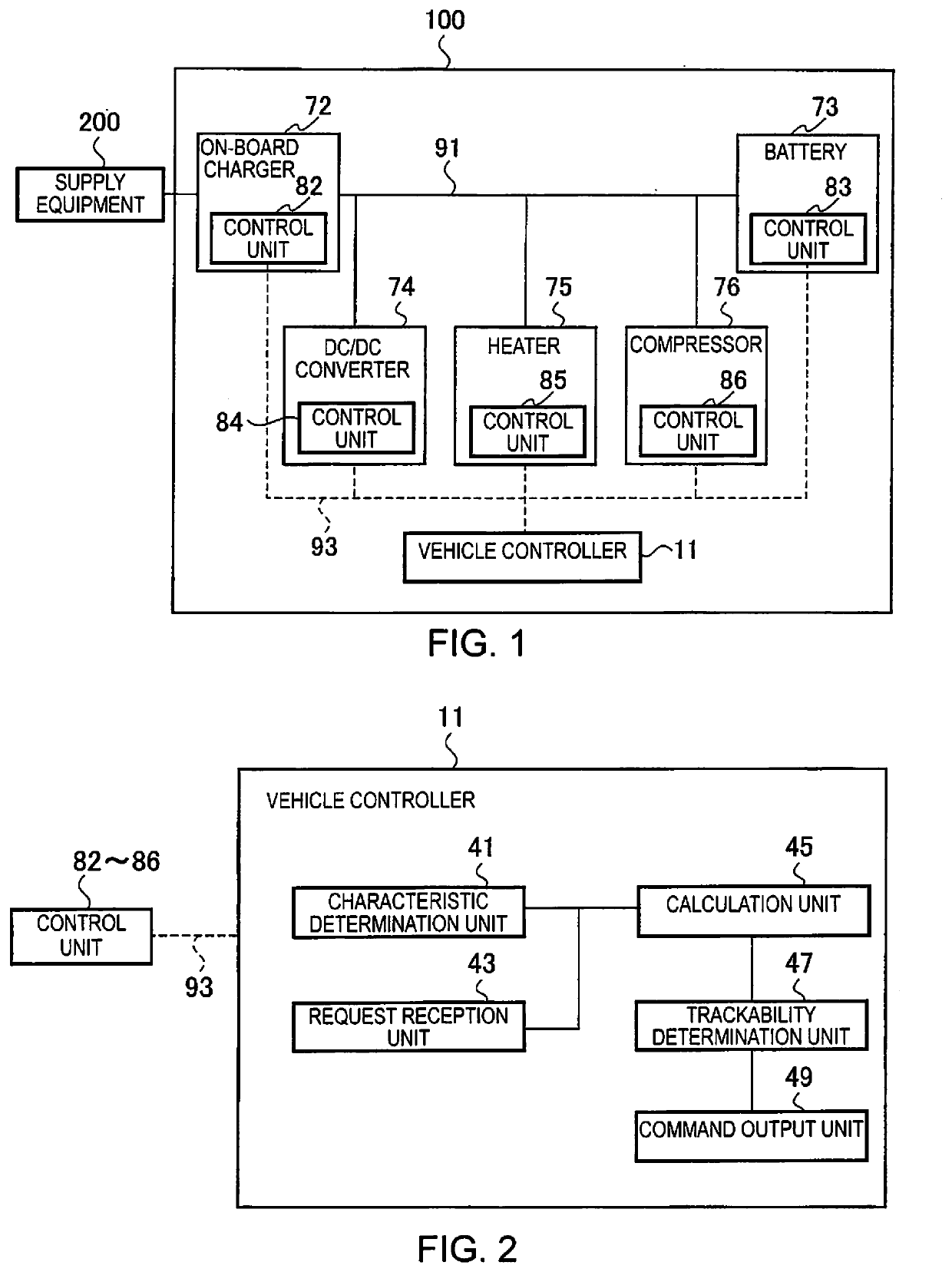
[0015]A current supply system including a current control device according to the present embodiment will be described with reference to FIG. 1. As shown in FIG. 1, current supply system 100 includes a vehicle controller 11 (current control device), an on-board charger 72, a battery 73, a DC / DC converter 74, a heater 75, and a compressor 76. The current supply system 100 is mounted in a vehicle, which is not shown.

[0016]The on-board charger 72, the battery 73, the DC / DC converter 74, the heater 75, and the compressor 76 are electrically connected via high-voltage system wiring 91 (high-voltage electrical system). Devices other than the battery 73 that are connected to the high-voltage system wiring 91 and that are sou...


PUM


Abstract

A current control method and a current control device is configured to control an on-board charger that supplies current to high-power components and a battery. When the on-board charger is controlled, the current control is executed to supply output current to the high-power components and the battery such that the output current is a sum of a drive current to be supplied to high-power components capable of computing current consumption based on their own operating states and the charging current to the battery.

Description

CROSS-REFERENCE TO RELATED APPLICATIONS[0001]This application is a U.S. national stage application of International Application No. PCT / IB2018 / 000381, filed on Mar. 15, 2018.BACKGROUNDTechnical Field[0002]The present invention relates to a current control method and a current control device for an on-board charger.Background Information[0003]Japanese Laid-Open Patent Application No. 2012-85519 (Patent Document 1) discloses a method for controlling an on-board charger that supplies DC charging current to a battery mounted in an electric vehicle, comprising setting a maximum DC charging current in accordance with a control signal indicating the electric current / power that the on-board charger can use, and supplying to a battery DC charging current up to the maximum DC charging current.SUMMARY[0004]In addition to a battery, high-power components are connected to the path that connects the on-board charger to the battery. If a high-power component is operating during charging of the bat...

Claims


Application Information

Patent Timeline
Patent Type & Authority Applications(United States)
IPC IPC(8): B60L53/62H02J7/00B60L50/64
CPCB60L53/62H02J7/00714B60L2240/549H02J2310/48B60L50/64H02J7/0068H02J7/00712Y02T90/12
Inventor EZAKI, MASATO
Owner NISSAN MOTOR CO LTD
Why Eureka
Try Eureka