Task processing system and task processing method

Inactive Publication Date: 2009-12-17
RENESAS ELECTRONICS CORP
View PDF12 Cites 11 Cited by
  • Summary
  • Abstract
  • Description
  • Claims
  • Application Information

AI Technical Summary

Benefits of technology

[0011]In the first aspect and the second aspect of the present invention, the main processor determines, by the end of the nth time segment, the operation frequency which the sub processor needs to execute the task within the (n+1)th time segment. The clock controller supplies the clock signal to the sub processor in the (n+1)th time segment, the clock signal according to the operation frequency determined by the main processor in the nth time segment. That is, the operation frequency is determined dynamically depending on the processing amount of the task to be executed in each time segment. This enables a flexible response to an increase or decrease in the processing amount in the next time segment. Also, this securely prevents supply of the clock signal based on an operation frequency with an operation margin being excessively secured. Accordingly, power consumption can be reduced.
[0012]Moreover, an increase in overhead or processing load can be prevented even in a system that frequently performs switching of frequency since a frequency dividing ratio is not determined for every interruption type.
[0013]With the present invention, power consumption can be reduced and an increase in overhead or processing load can be prevented even in a system that frequently performs switching of frequency.

Problems solved by technology

Therefore, the clock signal of a frequency higher than necessary is supplied to the sub processor even when the actual processing load is small in a certain time segment, causing electric power to be wasted.
Accordingly, increases in overhead and processing load become problems.

Method used


Image

  • Task processing system and task processing method
  • Task processing system and task processing method
  • Task processing system and task processing method

Examples


Embodiment Construction

[0018]Hereinafter, an embodiment applicable to the present invention will be described. Note that the present invention is not limited to the embodiment described below.

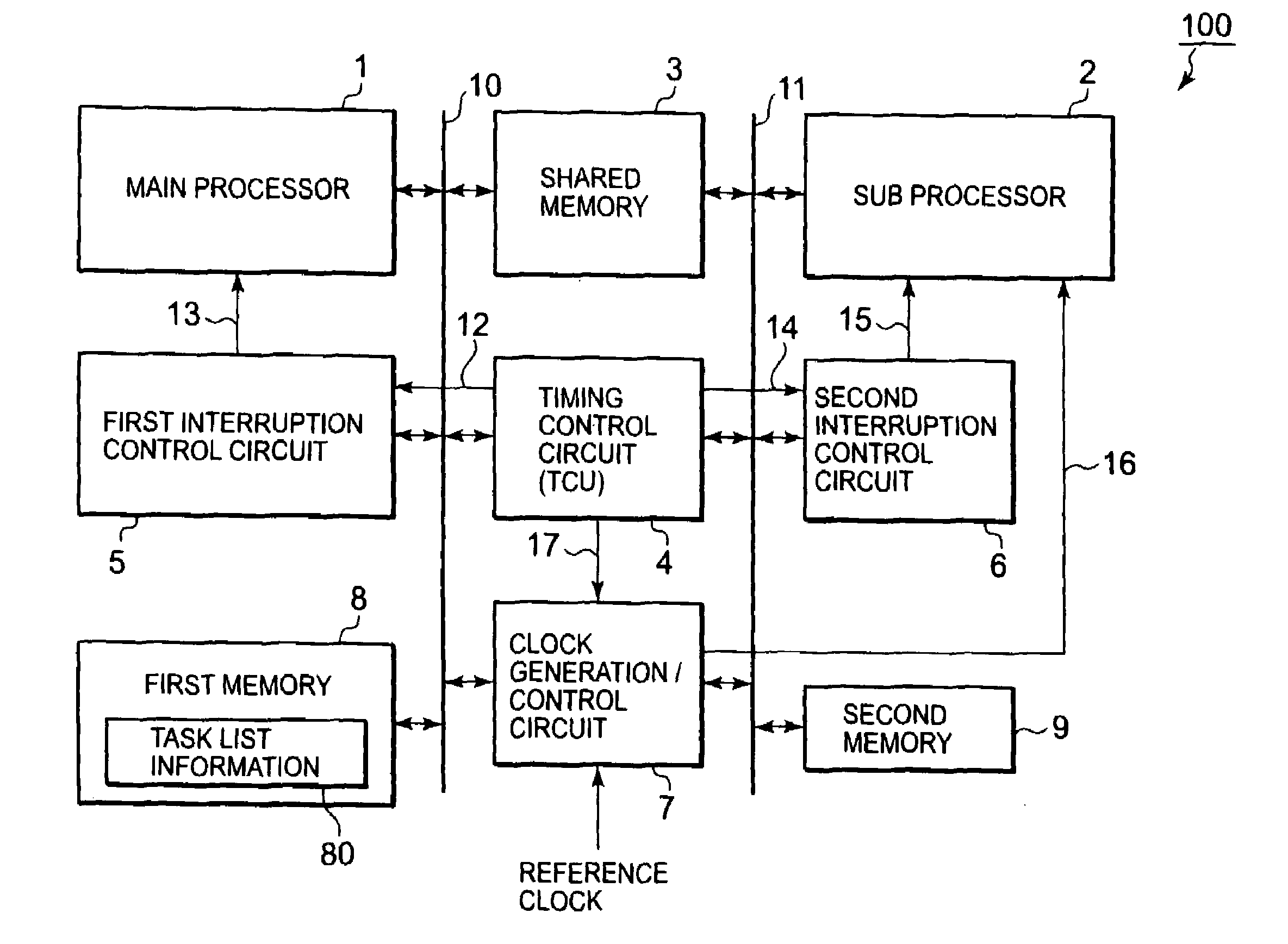
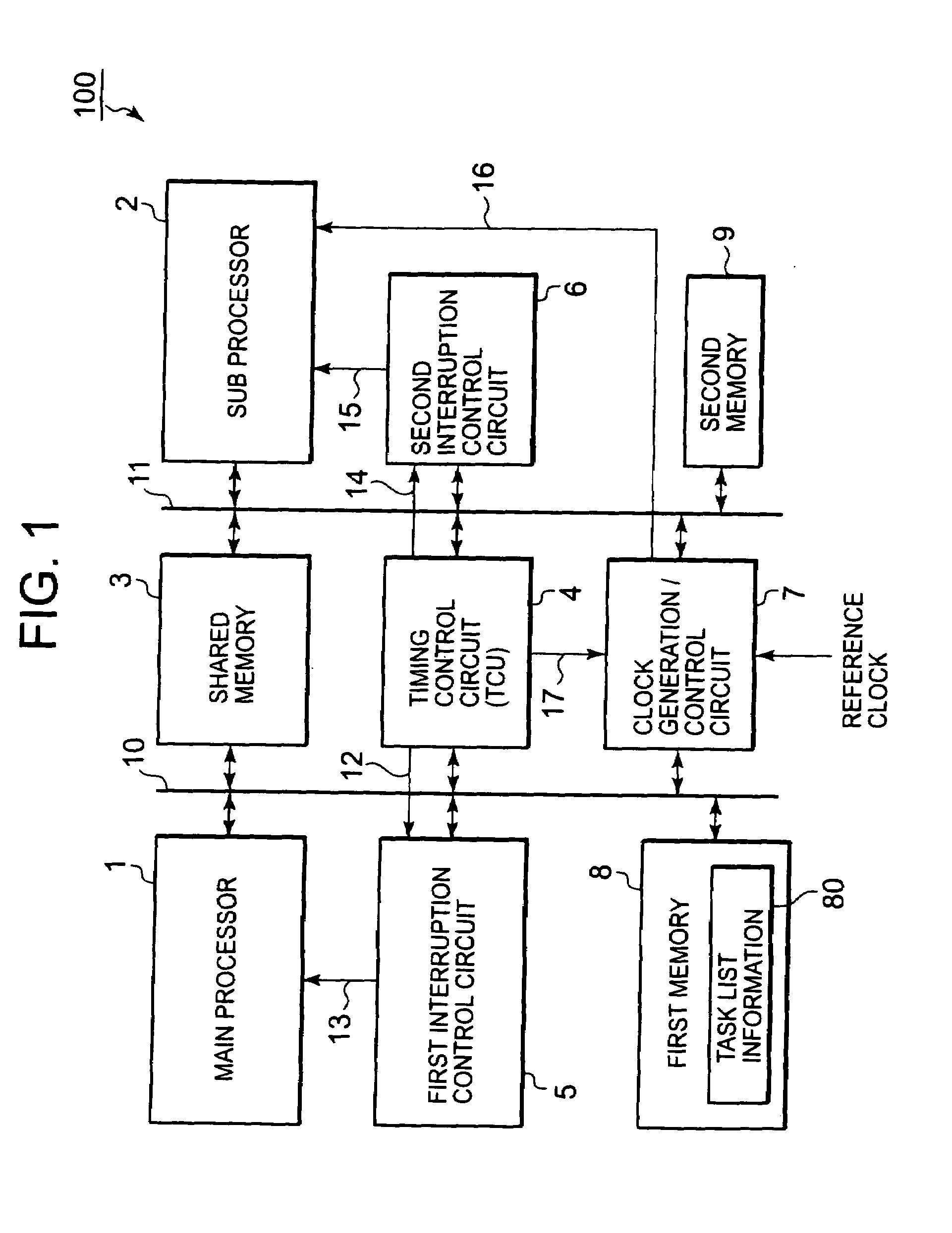
[0019]FIG. 1 shows one example of a task processing system 100 according to the embodiment of the present invention. The task processing system 100 is mounted to an electronic device such as a mobile phone.

[0020]As shown in FIG. 1, the task processing system 100 includes a main processor 1, a sub processor 2, a shared memory (task storage portion) 3, a timing control circuit (timing control unit (TCU)) 4, a first interruption control circuit 5, a second interruption control circuit 6, a clock generation / control circuit (clock controller) 7, a first memory (task list storage portion) 8, a second memory 9, and the like.

[0021]The main processor 1 is connected to the shared memory 3, the timing control circuit 4, the clock generation / control circuit 7, and the first memory 8 via a main processor bus 10.

[0022]The main pro...


PUM


Abstract

Provided are a task processing system and a task processing method that can reduce power consumption and prevent overhead or processing load from increasing even with a system which performs frequency switching frequently. A main processor determines at least one of tasks to be executed by a sub processor in each of a plurality of time segment each having a predetermined length and determines, by the end of an nth (n is an integer that satisfies n≧1) time segment, a clock frequency necessary for executing the task within an (n+1)th time segment based on information of a required number of cycles for the task to be executed by the sub processor in the (n+1)th time segment. The clock generation / control circuit supplies, in the (n+1)th time segment, to the sub processor a clock signal according to the clock frequency determined by the main processor in the nth time segment.

Description

BACKGROUND OF THE INVENTION[0001]1. Field of the Invention[0002]The present invention relates to a task processing system and a task processing method, particularly to a task processing system including a main processor and a sub processor controlled by the main processor, and a task processing method.[0003]2. Description of the Related Art[0004]Some task processing systems mounted to electronic devices such as mobile phones each include a main processor, a sub processor controlled by the main processor, and a clock supply circuit that supplies a clock signal to the sub processor. The main processor assigns a task to be executed by the sub processor to each of a plurality of time segments each having a predetermined length.[0005]Conventionally, an operation frequency allowing maximum expectable processings to be executed simultaneously has been determined in advance at the design stage. The clock supply circuit has supplied to the sub processor a clock signal based on the operation ...

Claims


Application Information

Patent Timeline
IPC IPC(8): G06F1/04G06F9/46
CPCG06F1/3203Y02B60/1217G06F1/324Y02D10/00G06F1/08
Inventor AZUMA, HIROYUKI
Owner RENESAS ELECTRONICS CORP
Why Eureka
Try Eureka