Traffic signal interpretation system and vehicle control system

a traffic signal and interpretation system technology, applied in the direction of vehicle position/course/altitude control, process and machine control, instruments, etc., can solve the problem that the vehicle action pattern obtained based only on the result of recognition of the lighting state of the traffic signal is not always appropria

Pending Publication Date: 2021-01-28
TOYOTA JIDOSHA KK
View PDF2 Cites 1 Cited by
  • Summary
  • Abstract
  • Description
  • Claims
  • Application Information

AI Technical Summary

Benefits of technology

[0029]According to the first aspect, the traffic signal interpretation system sets the action pattern of the vehicle with respect to the target area where the traffic signal is installed, based on the traffic signal state information, the corresponding pattern information, and the rule information. More specifically, the traffic signal interpretation system refers to the corresponding pattern information to acquire the action pattern corresponding to the lighting state indicated by the traffic signal state information as the provisional action pattern. The rule information indicates the rule that permits or prohibits a transition of the action pattern. When the provisional action pattern becomes one different from the previous action pattern, the traffic signal interpretation system sets the current action pattern by correcting the transition from the previous action pattern to the provisional action pattern so as to be consistent with the rule indicated by the rule information. It is thus possible to more appropriately set the action pattern with respect to the target area.
[0030]According to the second aspect, the traffic signal interpretation system sets the action pattern of the vehicle with respect to the target area where the traffic signal is installed, based on the traffic signal state information, the corresponding pattern information, and the surrounding vehicle information. More specifically, the traffic signal interpretation system refers to the corresponding pattern information to acquire the action pattern corresponding to the lighting state indicated by the traffic signal state information as the provisional action pattern. The surrounding vehicle information indicates the vehicle behavior of the surrounding vehicle with respect to the target area. The traffic signal interpretation system sets the action pattern by correcting the provisional action pattern so as to be consistent with the vehicle behavior of the surrounding vehicle. It is thus possible to more appropriately set the action pattern with respect to the target area.

Problems solved by technology

However, the vehicle action pattern obtained based only on a result of recognition of the lighting state of the traffic signal is not always appropriate.

Method used


Image

  • Traffic signal interpretation system and vehicle control system
  • Traffic signal interpretation system and vehicle control system
  • Traffic signal interpretation system and vehicle control system

Examples


first embodiment

1. First Embodiment

1-1. Traffic Signal Interpretation System

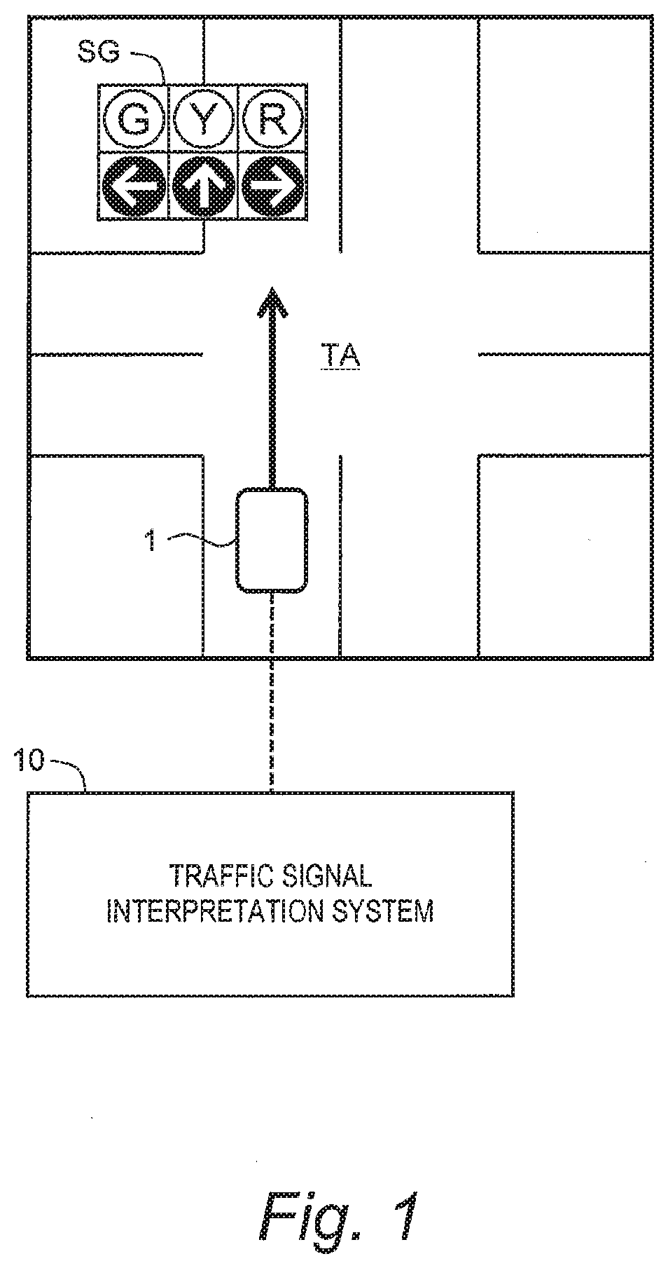
[0077]FIG. 1 is a conceptual diagram for explaining an outline of a first embodiment. A traffic signal SG (traffic light) is installed ahead of a vehicle 1. The vehicle 1 travels in accordance with a lighting state (signal indication) of the traffic signal SG. An area where the vehicle 1 should travel in consideration of the lighting state of the traffic signal SG is hereinafter referred to as a “target area TA.” That is, the target area TA is an area where the traffic signal SG is installed and which is subject to the lighting state of the traffic signal SG. The target area TA is exemplified by an intersection and its surroundings, a railroad crossing and its surroundings, a pedestrian crossing and its surroundings, and the like.

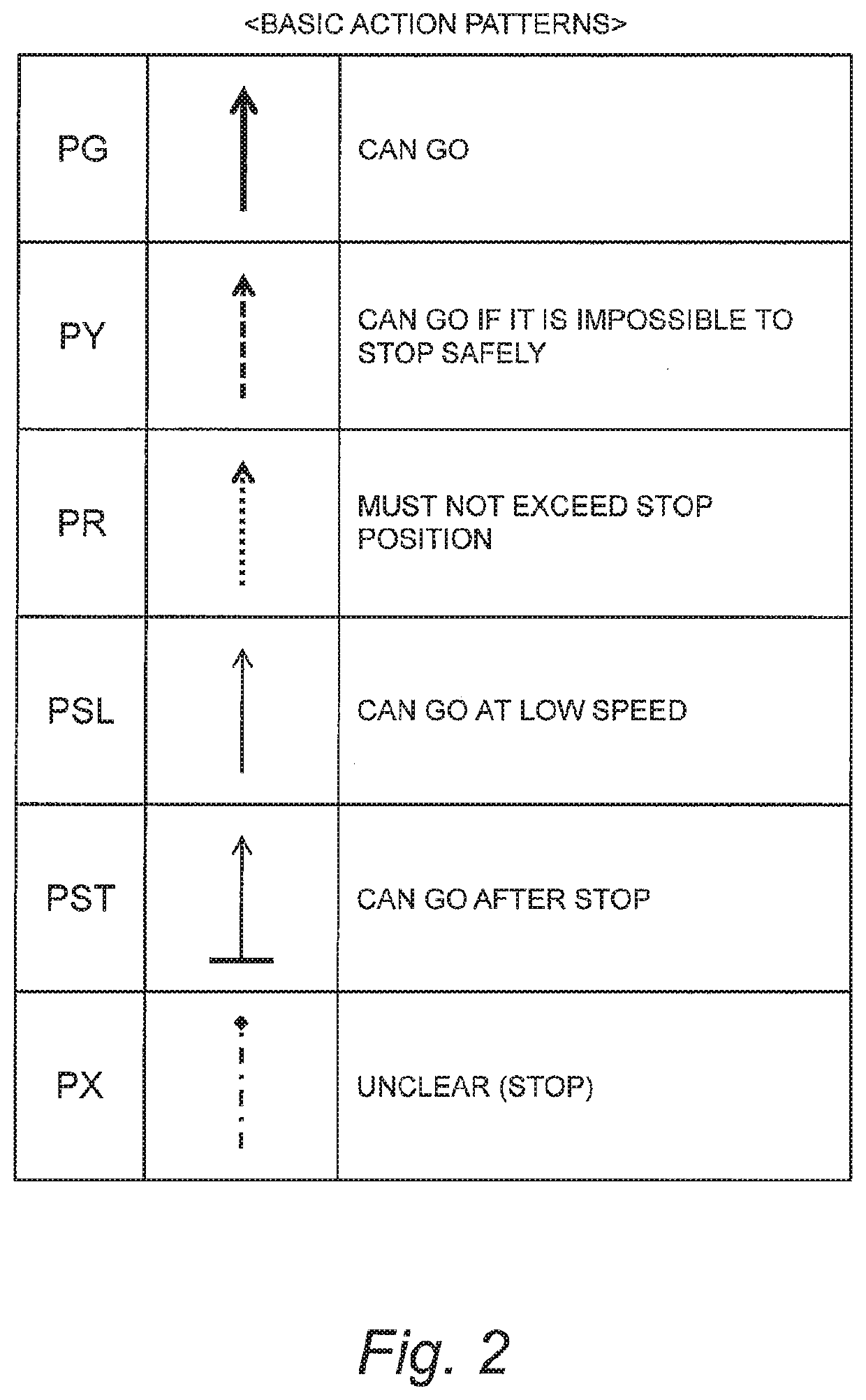
[0078]There are various patterns of a vehicle action with respect to the target area TA where the traffic signal SG is installed. Such the pattern of the vehicle action is hereinafter referred to a...

second embodiment

2. Second Embodiment

2-1. Outline

[0182]FIG. 21 is a block diagram showing a functional configuration example of the traffic signal interpretation system 10 according to a second embodiment. An overlapping description with the first embodiment will be omitted as appropriate. According to the present embodiment, the correction information CRC includes rule information RUL. The rule information RUL indicates a rule about a “transition (change) of the action pattern.” More specifically, the rule information RUL indicates a rule that permits or prohibits the transition of the action pattern.

[0183]FIG. 22 is a conceptual diagram for explaining an example of the rule information RUL. In the example shown in FIG. 22, the rule information RUL defines a rule about transitions between four action patterns PG, PY, PR, and PX. More specifically, a transition from the action pattern PG to the action pattern PY is permitted, and a transition from the action pattern PY to the action pattern PG is pr...

third embodiment

3. Third Embodiment

[0209]A third embodiment is a modification example of the second embodiment. The false recognition of the lighting state of the traffic signal SG may be caused by flicker or pseudo-lighting. In some cases, the false recognition of the lighting state ends after a short period of time and normal recognition is immediately recovered. The third embodiment provides the rule information RUL that enables flexibly reacting to such the short false recognition as well. An overlapping description with the foregoing embodiments will be omitted as appropriate.

3-1. Rule Information

[0210]FIG. 30 is a conceptual diagram for explaining an example of the rule information RUL according to the present embodiment. Basically, the transition from the action pattern PG to the action pattern PY is permitted and the transition from the action pattern PY to the action pattern PG is prohibited, as in the case of the second embodiment (see FIG. 22).

[0211]However, according to the present embo...


PUM


Abstract

A traffic signal interpretation system applied to a vehicle sets an action pattern of a vehicle with respect to a target area where a traffic signal is installed. Corresponding pattern information indicates a correspondence relationship between a lighting state of the traffic signal and the action pattern. Rule information indicates a rule that permits or prohibits a transition of the action pattern. The traffic signal interpretation system refers to the corresponding pattern information to acquire the action pattern corresponding to the lighting state as a provisional action pattern. When the provisional action pattern becomes one different from a previous action pattern, the traffic signal interpretation system sets a current action pattern by correcting a transition from the previous action pattern to the provisional action pattern so as to be consistent with the rule indicated by the rule information.

Description

CROSS-REFERENCE TO RELATED APPLICATION[0001]This application claims priority to Japanese Patent Application No. 2019-135524 filed on Jul. 23, 2019, the entire contents of which are herein incorporated by reference.BACKGROUNDTechnical Field[0002]The present disclosure relates to a traffic signal interpretation system that is applied to a vehicle executing automated driving and interprets a lighting state of a traffic signal to set a vehicle action pattern. In addition, the present disclosure relates to a vehicle control system having the traffic signal interpretation system.Background Art[0003]Patent Literature 1 discloses a method for detecting a traffic signal and its state. The method first scans a target area by using a sensor mounted on a vehicle to obtain information (image) of the target area. Here, the target area is a typical area in which a traffic signal exists. Subsequently, the method detects a traffic signal in the target area information to detect a position of the tra...

Claims


Application Information

Patent Timeline
Patent Type & Authority Applications(United States)
IPC IPC(8): B60W60/00B60W40/04G06K9/00B60W30/18
CPCB60W60/001B60W40/04B60W2050/0089B60W30/18154B60W2555/60G06K9/00825B60W40/02G05D1/0088G05D1/0231B60W2556/50G06V20/584B60W2554/4042B60W2554/4041B60W2554/4049B60W2520/14B60W2520/10B60W2520/105B60W2540/12B60W2540/10B60W2540/18B60W2556/45B60W2050/0075B60W2556/10
Inventor HAYASHI, YUSUKEKAWANAI, TAICHI
Owner TOYOTA JIDOSHA KK
Why Eureka
Try Eureka