Columnar-object-state detection device, columnar-object-state detection method, and columnar-object-state detection processing program

a detection program and object technology, applied in the field of collimnar object state detection devices, can solve the problems of for example, affecting the accuracy of central axis data correction, etc., and achieves the effects of easy acquisition, high accuracy, and accurate correction of central axis data

Active Publication Date: 2021-01-28
NIPPON TELEGRAPH & TELEPHONE CORP
View PDF0 Cites 11 Cited by
  • Summary
  • Abstract
  • Description
  • Claims
  • Application Information

AI Technical Summary

Benefits of technology

[0025]According to the first and second aspects of the columnar object state detection device according to one embodiment of the present invention, coordinate values of central axis data can be corrected without using new point cloud data or image data.
[0026]According to the third and fourth aspects of the columnar object state detection device described above, an appropriate type of a correction approximation equation can be selected.
[0027]According to the fifth aspect of the columnar object state detection device described above, missing coordinate values of the central axis data can be complemented.
[0028]According to the sixth aspect of the columnar object state detection device described above, the accuracy of correction of the central axis data can be calculated.
[0029]According to the seventh aspect of the columnar object state detection device described above, the inclination and the deflection of the central axis can be acquired without using new point cloud data or image data.
[0030]In other words, according to the present invention, a state of a columnar object can be easily acquired with high accuracy without using new point cloud data or image data for correcting data representing the state of the columnar object that is installed outdoors and is a management target.

Problems solved by technology

However, in any one of such techniques, a scanning device needs to be disposed at a short distance from a target object, and an operator needs to operate this device.
In addition, in order to acquire point cloud data using a 3D scanner and a laser scanner, there are problems of taking a scanning time of, for example, several minutes to several tens of minutes and the like.

Method used


Image

  • Columnar-object-state detection device, columnar-object-state detection method, and columnar-object-state detection processing program
  • Columnar-object-state detection device, columnar-object-state detection method, and columnar-object-state detection processing program
  • Columnar-object-state detection device, columnar-object-state detection method, and columnar-object-state detection processing program

Examples


Embodiment Construction

"d_n">[0052]Hereinafter, an embodiment of the present invention will be described with reference to the drawings.

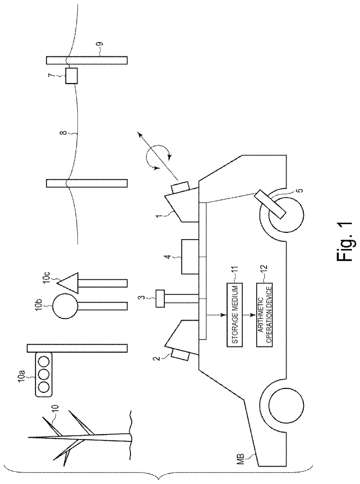
FIG. 1 is a schematic configuration diagram as one example of a columnar object state detection device according to an embodiment of the present invention.

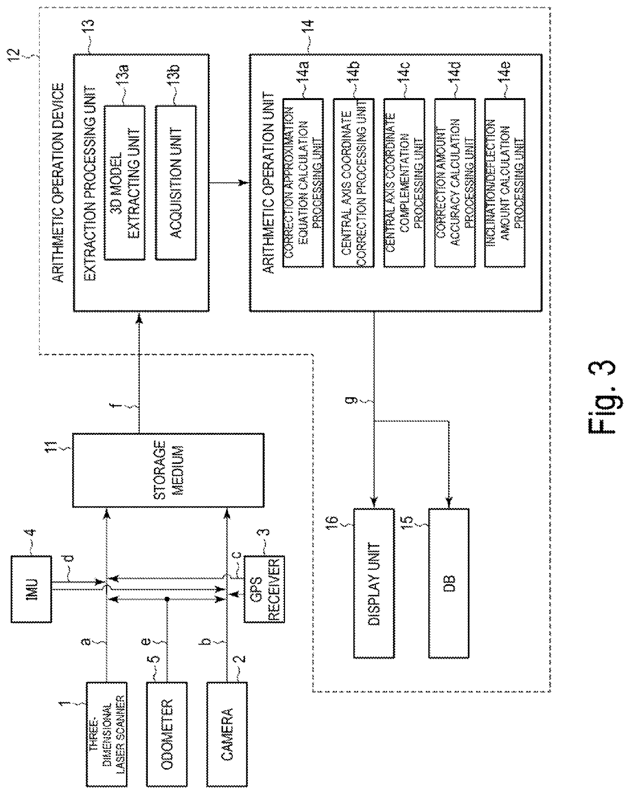
The columnar object state detection device is mounted in an inspection vehicle MB and includes a three-dimensional laser scanner 1 as a 3D laser surveying instrument, a camera 2, a GPS receiver 3, an IMU 4 as an inertial measurement unit, an odometer 5 as a traveling distance meter, a storage medium 11, and an arithmetic operation device 12. The columnar object state detection device acquires original measurement data (measurement data before correction) used for generating central axis data of a columnar model acquired by modeling columnar objects.

The storage medium 11 may be realized using a storage device such as a nonvolatile memory or the like. A plurality of three-dimensional laser scanners 1, cameras 2, and GPS r...


PUM


Abstract

A columnar object state detection device according to an embodiment is a device for detecting a state of a columnar object including: an acquisition unit configured to acquire central axis data that is an array of coordinate values of center points of the columnar object in a horizontal direction at a plurality of predetermined heights of the columnar object; an approximation equation calculating unit configured to calculate a correction approximation equation for correcting the coordinate values of the central axis data acquired by the acquisition unit through curve fitting for the array of coordinate values of the central axis data acquired by the acquisition unit; and correction unit configured to correct the coordinate values of the acquired central axis data using the correction approximation equation calculated by the approximation equation calculating unit.

Description

TECHNICAL FIELD[0001]The present invention relates to a columnar object state detection device, a columnar object state detection method, and a columnar object state detection processing program for detecting a state of a columnar object that is installed outdoors and becomes a target to be managed.BACKGROUND ART[0002]Conventionally, in order to measure states, for example, shapes of columnar objects, for example, poles (utility poles and the like), trees, or the like that are management targets installed outdoors, various scanning devices are used. For example, there are techniques such as (1) acquiring an image using a camera and performing the measurement described above using distances in the acquired image, (2) directly measuring a plurality of points on the surfaces of objects using a surveying instrument, (3) generating stereoscopic data from point cloud data received using a laser scanner and performing the measurement described above, and the like.However, in any one of suc...

Claims


Application Information

Patent Timeline
Patent Type & Authority Applications(United States)
IPC IPC(8): G01B11/24
CPCG01B11/24G01C15/00G01S17/89G01S7/4808G01S7/4802
Inventor GOTO, TAKASHIHONDA, RYUJIGOTO, YUKIHIROKAJIHARA, YOSHIYUKI
Owner NIPPON TELEGRAPH & TELEPHONE CORP
Why Eureka
Try Eureka