Vibration reduction mechanism and optical device

a technology which is applied in the field of vibration reduction mechanism and optical device, can solve the problems of insufficient regulation of the rotation of the lens frame body, and detrimental to the accuracy of the driving control of the vibration reduction mechanism, and achieve the effect of precise accuracy

Inactive Publication Date: 2010-06-22
NIKON CORP
View PDF7 Cites 8 Cited by
  • Summary
  • Abstract
  • Description
  • Claims
  • Application Information

AI Technical Summary

Benefits of technology

[0007]An object of the present invention is to provide a vibration reduction mechanism having a guide mechanism to guide a lens frame body, with a simple structure, and with high accuracy, and further to provide an optical device using the same.
[0013]In accordance with the present invention, there are provided, in the vibration reduction mechanism, the first and second engagement portions, both having groove-shaped portions to engage with the spherical or cylindrical-shaped portions of the following guide member, the above-mentioned first and second engagement portions being disposed both between the guide member and the first moving member and between the guide member and the second moving member. Therefore, the first and second moving members can be relatively moved by means of a simple structure along a two-axis direction, without any relative rotation, with a constant orientation, and with a precise accuracy.

Problems solved by technology

However, the above-mentioned vibration reduction mechanism has the disadvantage of including many constituent mechanical elements, thereby resulting in an insufficient regulation of the rotation of the lens frame body, due to errors and looseness between the constituent mechanical elements, which may be detrimental to the accuracy of the driving control of the vibration reduction mechanism.

Method used


Image

  • Vibration reduction mechanism and optical device
  • Vibration reduction mechanism and optical device
  • Vibration reduction mechanism and optical device

Examples


Embodiment Construction

[0020]In the following, referring to the drawings, an embodiment of the present invention is described in more detail.

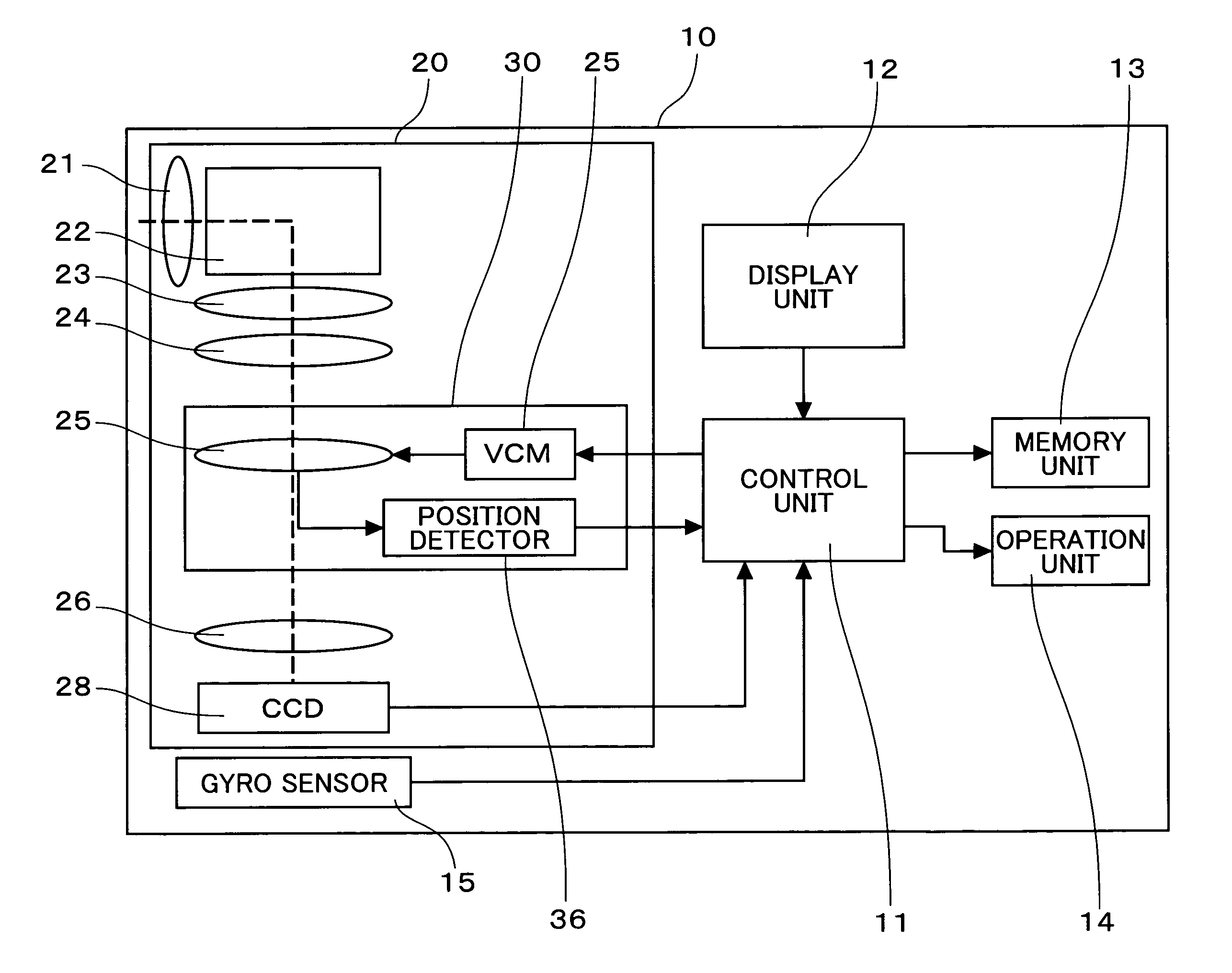
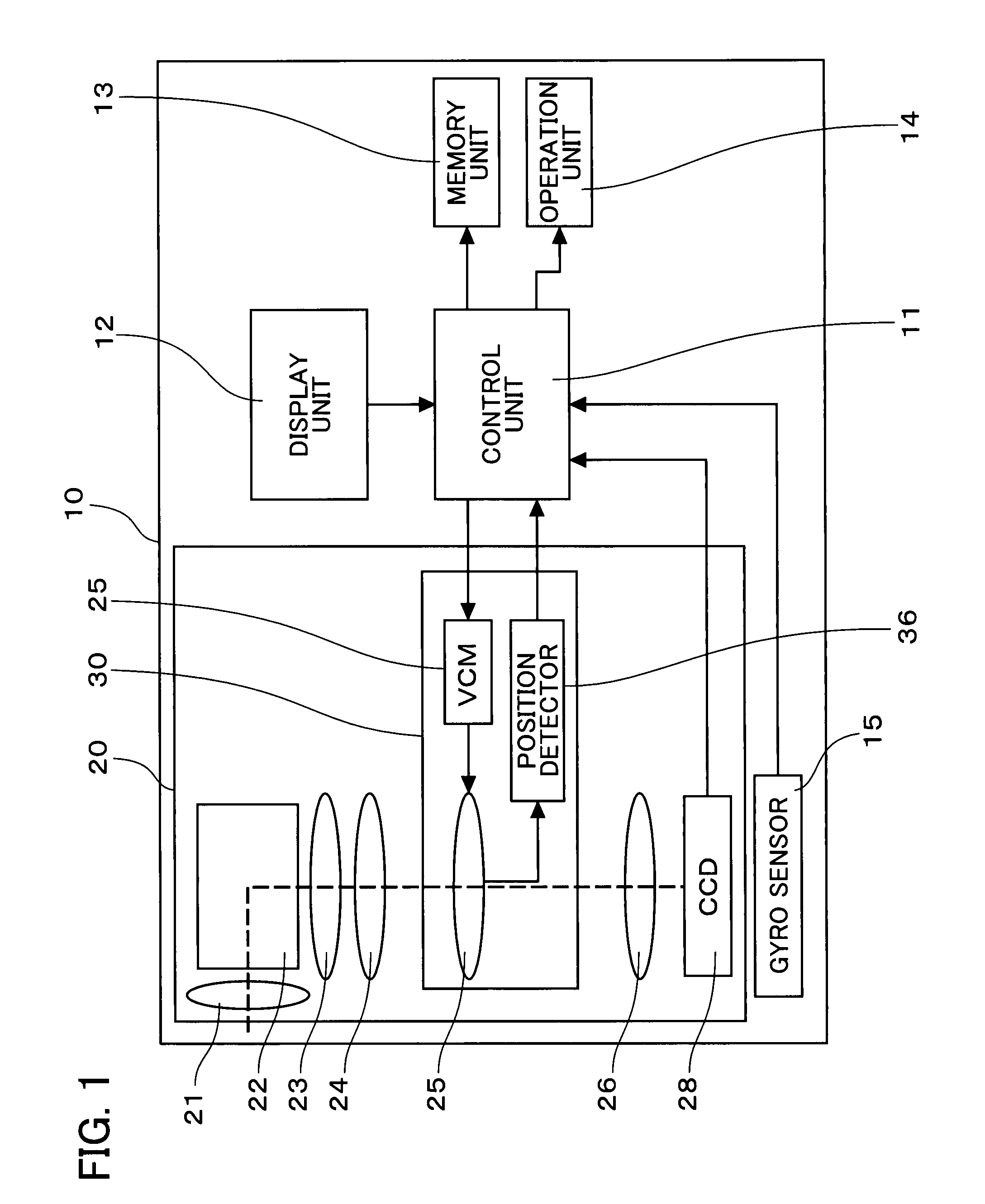
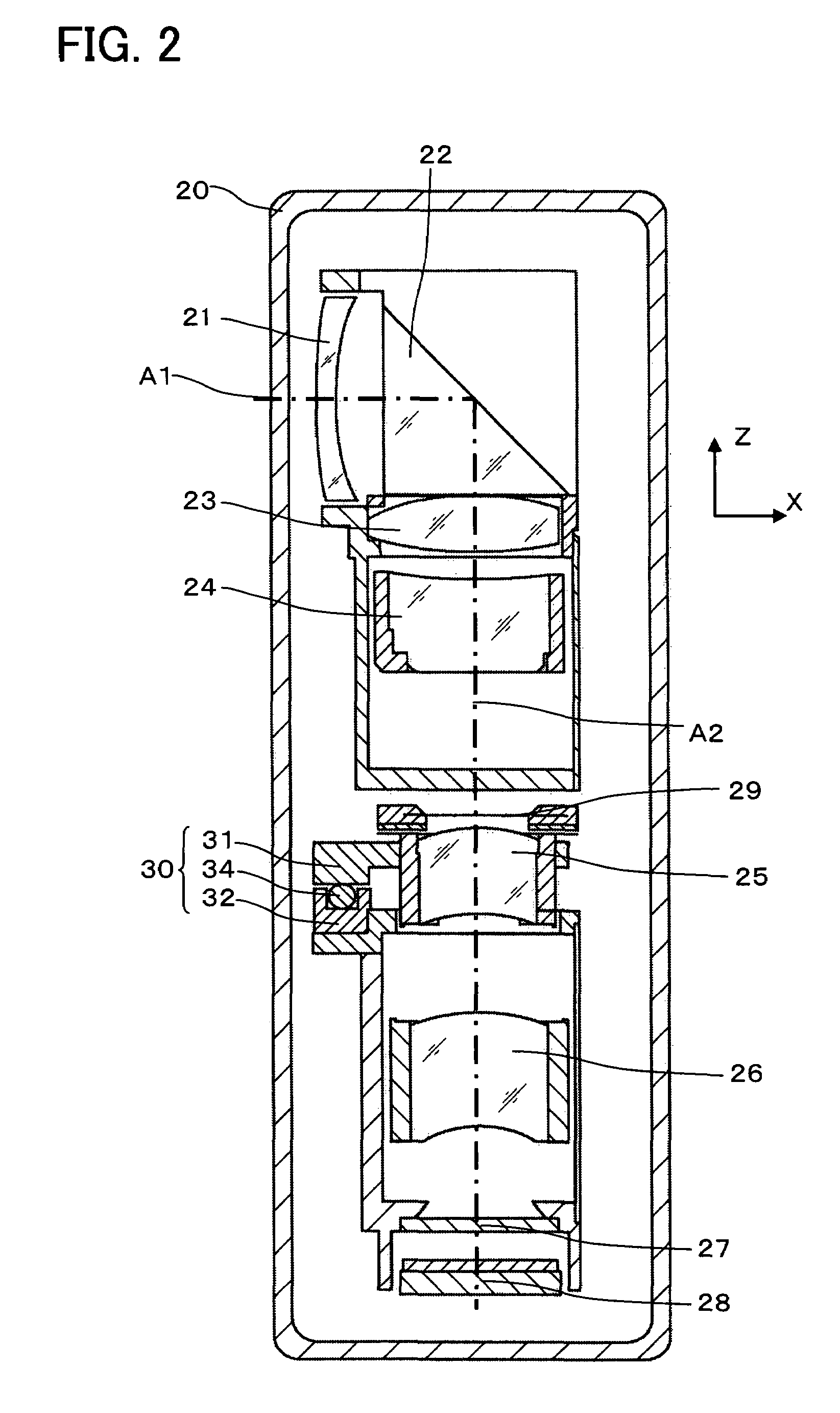
[0021]FIG. 1 is a block diagram showing an embodiment of a camera as a whole in accordance with the present invention. FIG. 2 shows a lens barrel unit of the camera. FIG. 3 is a plain view showing a vibration reduction mechanism provided in a lens barrel unit. FIG. 4 is an A-A cross sectional view of FIG. 3. FIG. 5A and FIG. 5B show a B-B cross sectional view of FIG. 3. FIG. 6 is a perspective view of a guide member of the vibration reduction mechanism. For clarity, in FIG. 2 through FIG. 5B, the direction of light A1 which incidents to the camera 10 from a subject is shown as X direction, while the direction of the light A2 orthogonal to the light A1 is shown as the Z direction. Further, the Y direction is orthogonal both to the X direction and Z direction.

[0022]A camera 10 as shown in FIG. 1 is a digital camera including: a control unit 11; a display unit 12; a mem...


PUM


Abstract

A vibration reduction mechanism, comprising: a first moving member and a second moving member which move relatively at a time of image blur correction; a guide member which guides relative movements of the first moving member and the second moving member; a plurality of first engagement portions, aligned in a row, which engage the first moving member with the guide member by spherical or cylindrical surfaces and groove-shaped portions; and a plurality of second engagement portions, aligned in a row, which engage the second moving member with the guide member by spherical or cylindrical surfaces and groove-shaped portions, wherein a groove shape of at least either one of the plurality of the first engagement portions or the plurality of the second engagement portions is formed with an elongated hole shape extending along an alignment direction of the first engagement portions aligned in a row.

Description

[0001]The disclosure of the following priority applications is herein incorporated by reference: Japanese Patent Application No. 2006-279579 filed on Oct. 13, 2006.BACKGROUND OF THE INVENTION[0002]1. Field of the Invention[0003]The present invention relates to a vibration reduction mechanism having a mechanism to correct blur of an optical system and an optical device using the vibration reduction mechanism.[0004]2. Description of Related Art[0005]There is known an optical device provided with a vibration reduction mechanism, in which a lens frame body is movable along a prescribed direction by sliding on a guide axis and rotates around the guide axis so that lens is supported to be movable along a direction perpendicular to the prescribed direction (for example, refer to Japanese Unexamined Patent Application Publication No. H10-3102).[0006]However, the above-mentioned vibration reduction mechanism has the disadvantage of including many constituent mechanical elements, thereby resu...

Claims


Application Information

Patent Timeline
Patent Type & Authority Patents(United States)
IPC IPC(8): G03B17/00H04N5/228
CPCG02B27/646G03B5/00G03B17/00G03B2217/005G03B2205/0007G03B2205/0015G03B2205/0053
Inventor OMI, JUNICHI
Owner NIKON CORP
Why Eureka
Try Eureka