Method for activiating a clutch

a technology of clutch and actuator, applied in the field of clutch actuator, can solve the problems of strong hysteresis effect, and achieve the effect of accurate adjustmen

Inactive Publication Date: 2010-03-04
ZF FRIEDRICHSHAFEN AG
View PDF13 Cites 7 Cited by
  • Summary
  • Abstract
  • Description
  • Claims
  • Application Information

AI Technical Summary

Benefits of technology

[0005]Based on this, it is an object of the invention to create a novel method for actuating a clutch, with which the actuating accuracy of the torque to be transmitted by the clutch can be more accurately adjusted.

Problems solved by technology

One disadvantage of the torque-based, pressure-based or force-based clutch torque specifications known from the state of the art is that strong hysteresis effects occur, which strongly influence the actuating accuracy of the torque to be transmitted by the clutch.

Method used


Image

  • Method for activiating a clutch
  • Method for activiating a clutch
  • Method for activiating a clutch

Examples


Embodiment Construction

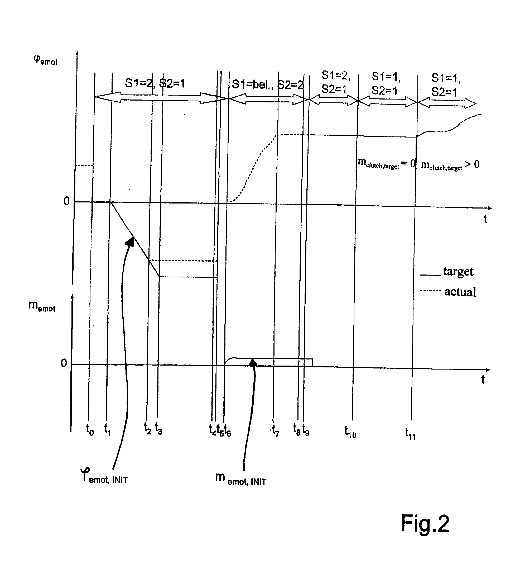
[0019]A first exemplary embodiment of the method of the invention for actuating a continuously variable clutch of a drive train is described in the following with reference to FIGS. 1 and 2.

[0020]In the exemplary embodiment of FIGS. 1 and 2, adjustment of the torque to be transmitted by the clutch is carried out electromechanically with the aid of an electric motor by utilizing the position-dependent clutch torque specification according to the invention.

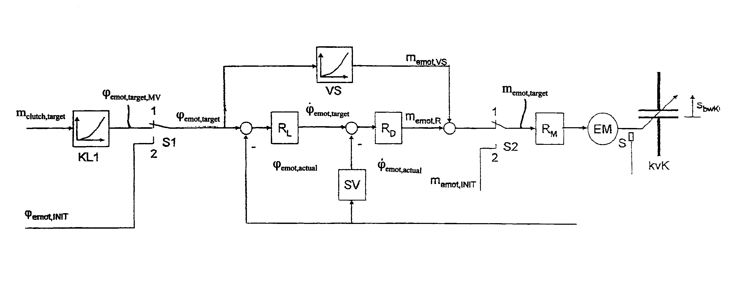
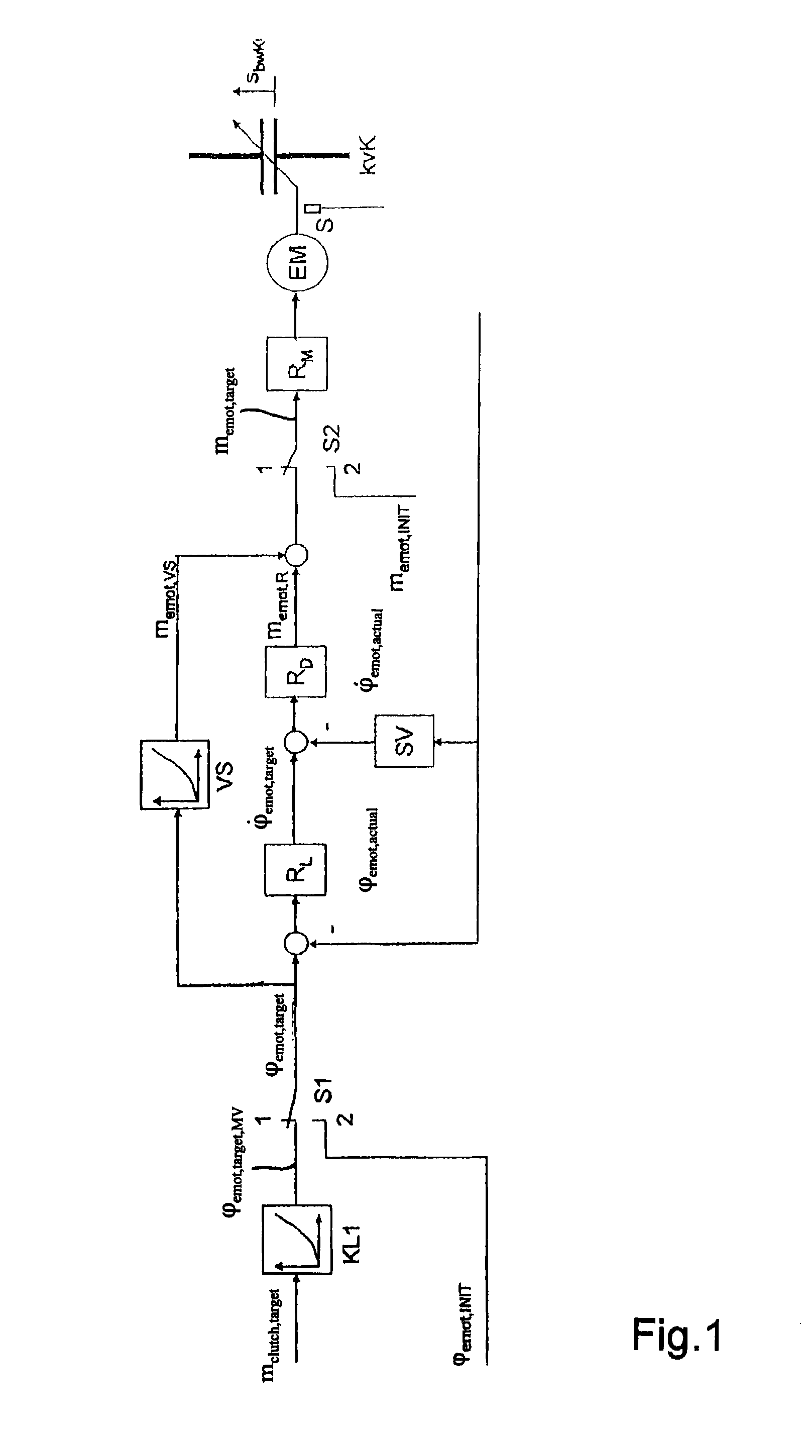
[0021]FIG. 1 shows thus a control loop structure of the first exemplary embodiment of the method according to the invention, wherein a continuously variable clutch kvK is actuated, as already mentioned, via an electric motor EM. The position-dependent clutch torque specification is realized by means of a cascaded position control, wherein the cascaded position control according to FIG. 1 is carried out via a cascaded or mutually nested electric motor position control, electric motor speed control and electric motor torque control.

[0...


PUM


Abstract

A method for actuating a continuously variable clutch such that the torque to be transmitted by the clutch is continuously adjusted either electromechanically via an electromotive drive, hydraulically via a pressure actuator, or electromagnetically via an electromagnetic actuator. The torque transmitted by the clutch is adjusted by utilizing a position-dependent clutch torque specification.

Description

[0001]This application is a National Stage completion of PCT / EP2007 / 061855 filed Nov. 5, 2007, which claims priority from German patent application serial no. 10 2006 056 515.0 filed Nov. 30, 2006.FIELD OF THE INVENTION[0002]The invention relates to a method for actuating a clutch.BACKGROUND OF THE INVENTION[0003]In continuously variable clutches of a drive train known from the state of the art, torque to be transmitted by the clutch is actuated either electro-mechanically via an electromotive drive, hydraulically via a pressure actuator, electromagnetically via an electromagnet, or continuously adjusted via an electromagnetic force actuator. For this purpose, in the known clutches the torque to be transmitted by the clutch is adjusted via a motor torque of the electric motor, via a clutch pressure of the pressure actuator or via an attractive force of the electromagnet, wherein when more clutch torque is to be transmitted, a greater motor torque, a greater clutch pressure or a grea...

Claims


Application Information

Patent Timeline
Patent Type & Authority Applications(United States)
IPC IPC(8): F16D48/06
CPCF16D48/06Y10T477/78Y10T477/753Y10T477/76F16D2500/3021F16D2500/3023F16D2500/3026F16D2500/3027F16D2500/30426F16D2500/50245F16D2500/70264F16D2500/7044
Inventor ZDYCH, ROBERTGROMUS, MICHAELGRANZOW, CLAUS
Owner ZF FRIEDRICHSHAFEN AG
Why Eureka
Try Eureka