
Ultrasonic measuring device for the measurement on a flowing fluid and ultrasonic measuring system

a technology of ultrasonic and measuring device, which is applied in the direction of liquid/fluent solid measurement, volume metering, instruments, etc., can solve the problems of high demands on purity and/or integrity, ultrasonic signals must be introduced in the fluid obliquely, and the cleaning or sterilization of the measuring device is a very large expenditure of time, material and cost,

Active Publication Date: 2021-01-28
LEVITRONIX
View PDF0 Cites 2 Cited by
  • Summary
  • Abstract
  • Description
  • Claims
  • Application Information

AI Technical Summary

Benefits of technology

The present invention provides a design for a pipe system that allows for fluid flow without being influenced by turbulences or deposits. The system is compact and space-saving. However, there may be problems in detecting ultrasonic signals due to the oblique angle at which the signals propagate in the fluid. Additionally, the measuring section is relatively short, resulting in lower time resolution. The invention also provides a reusable device with a projection that engages in a recess in the single-use device for easy placement and removal.

Problems solved by technology

In particular for measurements on very sensitive or very aggressive substances, the cleaning or sterilization of the measuring device represents a very large expenditure of time, material and costs.
A disadvantage of this design is that the ultrasonic signals must be introduced into the fluid obliquely to the flow direction.
The angle at which the ultrasonic signal propagates in the fluid after penetrating the pipe wall depends on the properties of the fluid, which can cause problems in detecting the ultrasonic signal.
In addition, the measuring section is relatively short in this design, which results in a lower time resolution.
A disadvantage of this design is that the fluid is deflected twice by 90° as it passes through the measuring tube, namely at the transition from the inlet tube to the central section and at the transition from the central section to the outlet tube.
This double deflection causes turbulence and cavitation in the fluid as well as stagnations or even deposits of the fluid, in particular in the critical corner areas of the measuring tube.
These effects particularly reduce the accuracy and reliability of the measurement.
A further disadvantage of this design is its space requirement.
The double bending of the measuring tube requires considerably more space for the measuring device.
This means that the fluid flows symmetrically around both ultrasonic transducers, resulting in a particularly low influence on the flow of the fluid.

Method used


Image

  • Ultrasonic measuring device for the measurement on a flowing fluid and ultrasonic measuring system
  • Ultrasonic measuring device for the measurement on a flowing fluid and ultrasonic measuring system
  • Ultrasonic measuring device for the measurement on a flowing fluid and ultrasonic measuring system

Examples


first embodiment

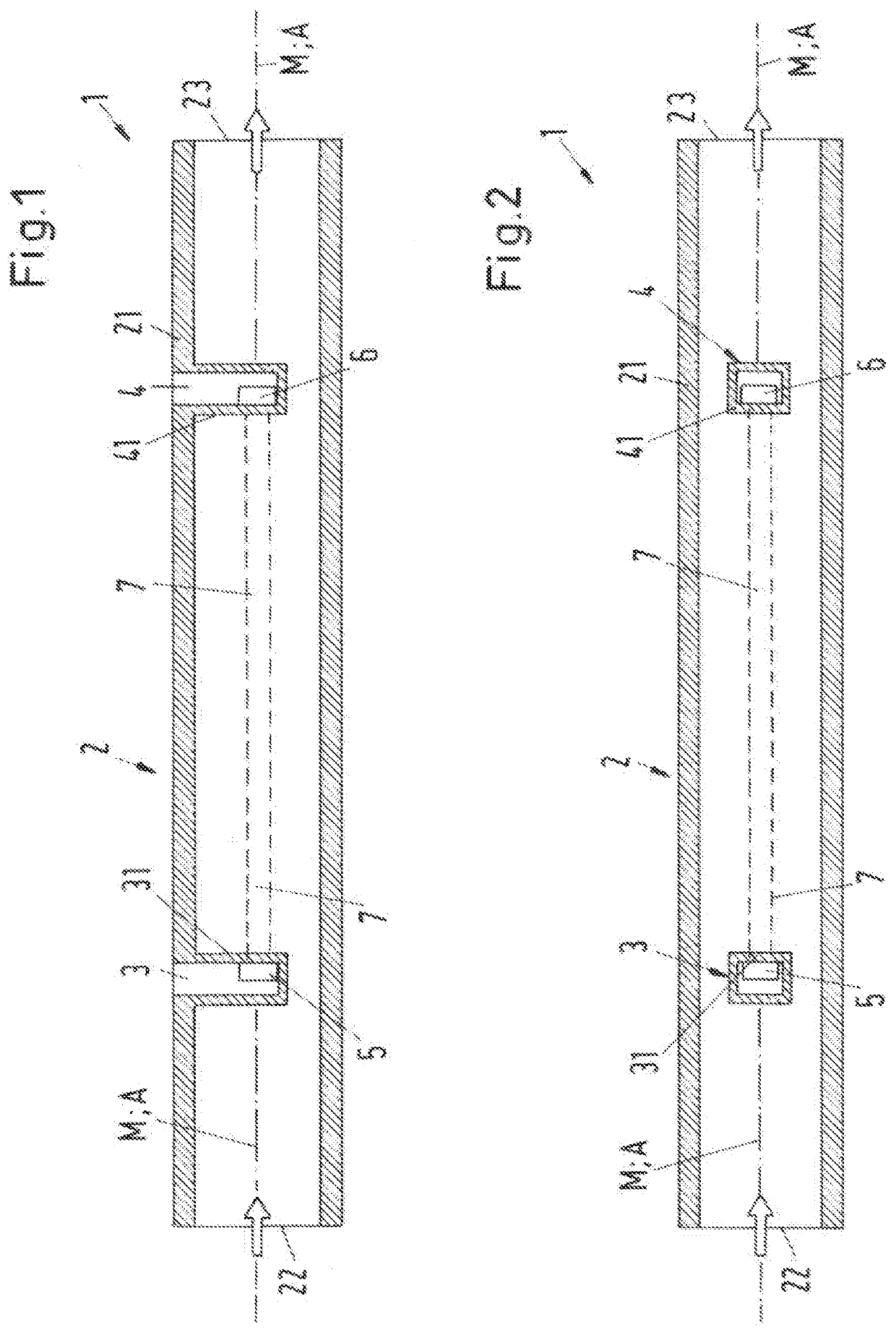
[0086]In the first embodiment, the first chamber 3 and the second chamber 4 are each designed as an inversion in the wall 21 of measuring tube 2. The first chamber 3 and the second chamber 4 are therefore each a recess in the wall 21 of the measuring tube 2, directed into the interior of the measuring tube 2. The first chamber and the second chamber 4 are each so deep that the first ultrasonic transducer 5 and the second ultrasonic transducer 6 can be arranged on the central axis M of the measuring tube 2. At the same time, the two ultrasonic transducers 5, 6 are protected from a contact with the fluid by the wall of the respective chamber 3 or 4.

[0087]The first chamber 3 is bounded on its side facing away from the inlet 22 by a first wall 31, which is designed as a planar, i.e. unbent wall, and which is perpendicular to the central axis M of the measuring tube 2 and thus perpendicular to the flow direction A. The first ultrasonic transducer 5 is arranged in the first chamber 3 on t...

fourth embodiment

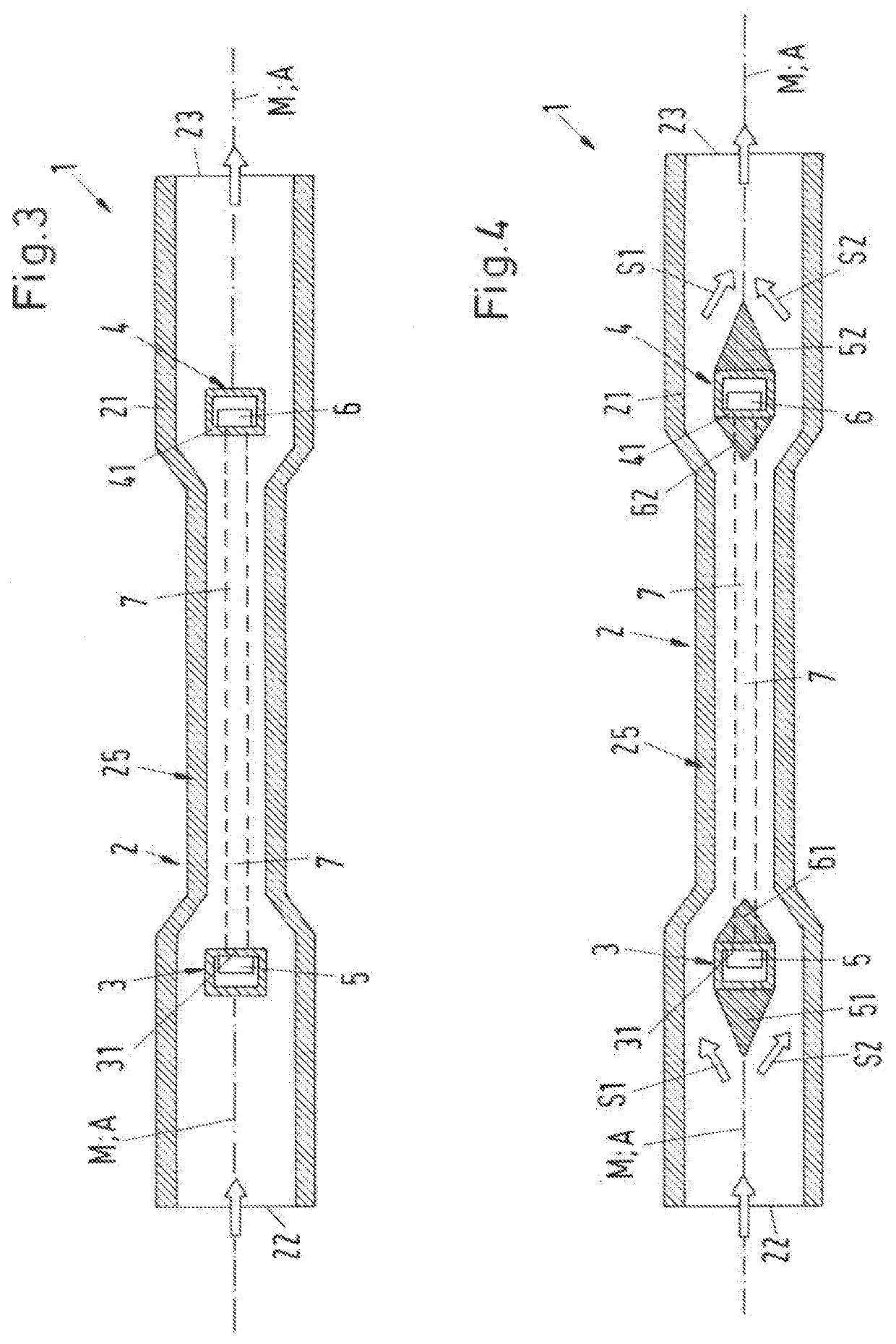
[0109]In the ultrasonic measuring device 1 according to the invention, the first chamber 3 has a first flow guiding element 51 on its side facing the inlet 22, which is designed in such a way that it divides the fluid flow in front of the first chamber 3, viewed in the flow direction A, as gently as possible into two partial flows S1 and S2, of which one, namely the partial flow S1, is guided around above the first chamber 3, according to the representation, and the other, namely the partial flow S2, is guided around below the first chamber 3, according to the representation. For this purpose, the first flow guiding element 51, for example, has a triangular cross-section when viewed in the flow direction A, and in particular the cross-section of an isosceles triangle, the tip of which faces the inlet 22 and the base of which lies flush with the first chamber 3. Due to this design, the fluid is divided into two essentially equally strong partial flows S1, S2 and undesirable flow phen...

fifth embodiment

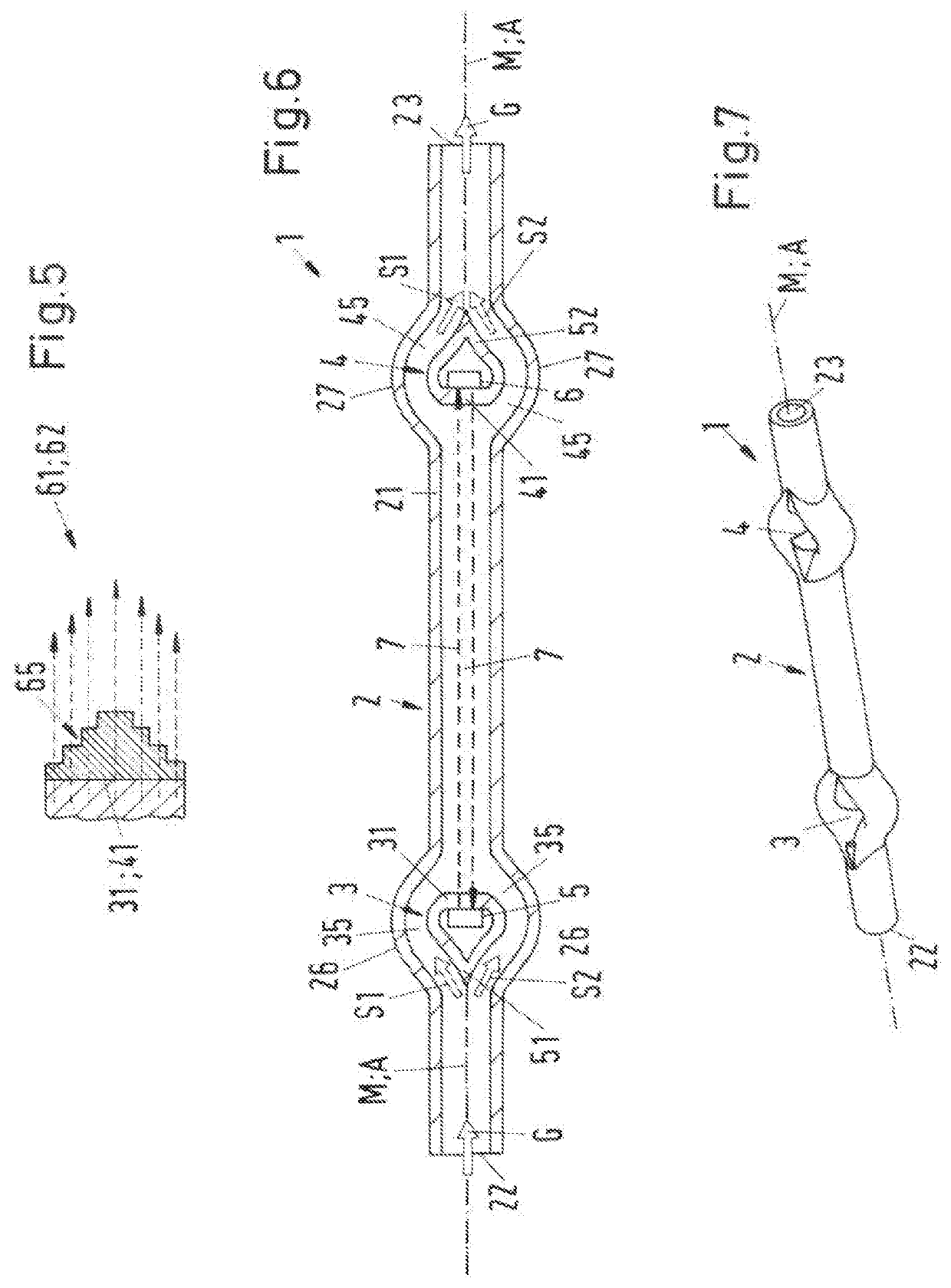
[0117]For better understanding, FIG. 7 additionally shows a perspective view of the ultrasonic measuring device 1 according to the invention.

[0118]In the fifth embodiment of the ultrasonic measuring device 1 according to the invention, the first chamber 3 and the second chamber 4 are each designed in such a way that the first flow guiding element 51 is an integral part of the first chamber 3 and the second flow guiding element 52 is an integral part of the second chamber 4.

[0119]For this purpose, the first chamber 3 and the second chamber 4 are each designed such that they each have a substantially drop-shaped profile when viewed in the flow direction A. The tip of the drop-shaped profile of the first chamber 3 is directed towards the inlet 22 and the tip of the drop-shaped profile of the second chamber 4 is directed towards the outlet 23. The bottom of the drop-shaped profile forms the first wall 31 at the first chamber 3 and the second wall 41 at the second chamber, wherein the fi...


PUM


Abstract

An ultrasonic measuring device for the measurement of a flow of a fluid, includes a measuring tube, a first chamber and a second chamber. The measuring tube has a central axis, which defines a flow direction for the fluid; The first chamber has a first ultrasonic transducer arranged therein. The second chamber has a second ultrasonic transducer arranged therein. The measuring tube includes an inlet and an outlet for the fluid. The first ultrasonic transducer and the second ultrasonic transducer bound a rectilinear measuring section for the fluid, the first chamber and the second chamber being configured and arranged such that the fluid is capable of flowing around each of them. The first ultrasonic transducer and the second ultrasonic transducer are arranged such that the measuring section extends in the flow direction.

Description

CROSS-REFERENCE TO RELATED APPLICATION[0001]This application claims priority to European Patent Application No. 19188626.6, filed Jul. 26, 2019, the contents of which are hereby incorporated herein by reference in their entirety.BACKGROUNDField of the Invention[0002]The invention relates to an ultrasonic measuring device for the measurement of a fluid flow and to an ultrasonic measuring system.Background Information[0003]Conventional ultrasonic measuring devices for the measurement of a fluid flow are used for example to determine the flow of the fluid through a pipe, for example a flexible or a hard plastic hose. In particular with flexible hoses, it is a well-known measure to design the measuring device as a clamping device such that it can be clamped onto a flexible pipe or that the pipe can be clamped by the measuring device. The pipe with the fluid flowing in it is then applied with ultrasonic signals. After passing through the pipe and the fluid, the ultrasonic signals are rec...

Claims


Application Information

Patent Timeline
Patent Type & Authority Applications(United States)
IPC IPC(8): G01F1/66
CPCG01F1/662G01F1/667G01N29/024G01N29/032G01D21/02G01N2291/011G01N2291/015G01F1/668G01F15/00G01N2291/02836G01N29/222G01N2291/02809G01N2291/02433G01N2291/02818G01N2291/102G01F25/10
Inventor WELSCH, GUIDOBOBER, MACIEJWEBER, JONATHAN
Owner LEVITRONIX
Learn More