Pinch valve

Pending Publication Date: 2021-02-04
CARTEN CONTROLS LTD
View PDF1 Cites 0 Cited by
  • Summary
  • Abstract
  • Description
  • Claims
  • Application Information

AI Technical Summary

Benefits of technology

This patent describes a valve assembly that can be customized by the end user without needing to replace the entire assembly. The assembly includes interchangeable parts, such as a compressor and holder, that can be easily installed and replaced. This design allows for flexibility and adaptability, and can be used with different fluid conduit sizes and wall thicknesses. The components are durable and can be easily fabricated into various shapes to suit different conduit profiles. The technical effects of this patent are improved customization flexibility, durability, and adaptability for various fluid conduit shapes and profiles.

Problems solved by technology

Isolation of the living cells or components within a given process is of the utmost importance as contamination can render products unsuitable for use.
Single-use polymeric devices are not durable devices, and are generally rated for use with one production batch only.
They are not designed to provide a reusable assembly.
In addition, little or no control can be provided to achieve a desired flow rate for transfer of media.
However, the significant number of single use tubing sizes—determined by the tubing inner diameter—and differing tubing wall thickness available to the market, render stainless-steel valve assemblies for all single-use tubing sizes impractical and cost inefficient for both equipment manufacturer and end user.

Method used


Image

  • Pinch valve
  • Pinch valve
  • Pinch valve

Examples


Embodiment Construction

[0031]The invention will now be described with reference to the accompanying figures.

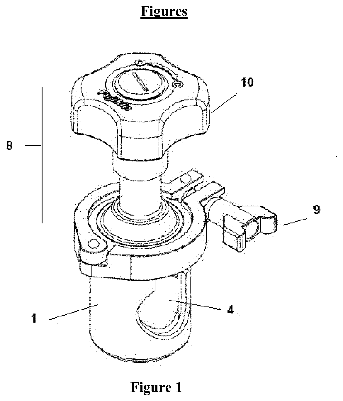
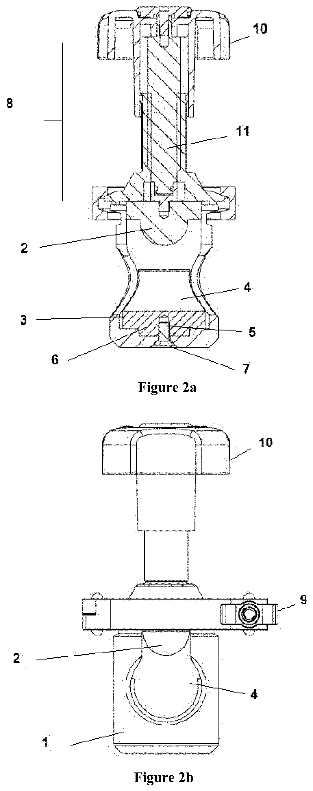
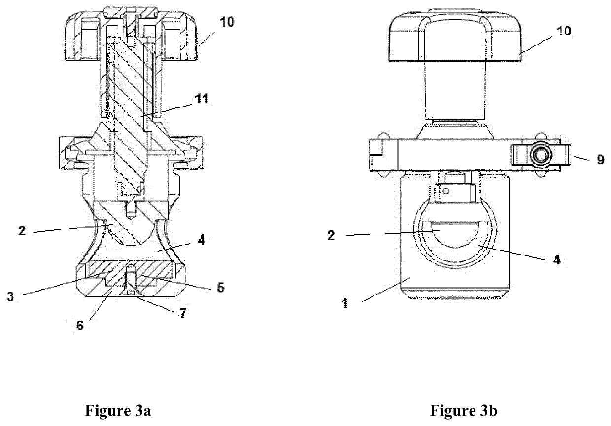
[0032]FIGS. 1 to 6 show the pinch valve assembly of the invention for compression of a fluid conduit. The pinch valve assembly comprises an assembly housing 1; an interchangeable compressor 2; an interchangeable holder 3 for holding a fluid conduit, the holder 3 is positioned facing the interchangeable compressor 2.

[0033]The pinch valve assembly is configured such that the compressor 2 is moveable towards the holder 3 within the assembly housing 1 for compression of a fluid conduit which can be placed in an opening 4 in the housing 1 between the compressor 2 and the holder 3.

[0034]The compressor 2 is moveable between an open position (Seen in FIGS. 2a and 2b, 5a and 5b) wherein a fluid conduit (not shown) placed in the opening 4 between the compressor 2 and the holder 3 is uncompressed and a closed position (Seen in FIGS. 3a and 3b, 6a and 6b) wherein a fluid conduit placed in the opening 4 between ...


PUM


Abstract

A pinch valve assembly is provided for compression of a fluid conduit comprising an assembly housing (1); an interchangeable compressor element (2); an interchangeable holder element (3) for holding a fluid conduit, the holder element facing the interchangeable compressor element; the valve assembly being configured such that the compressor element is moveable towards the holder element within the assembly housing for compression of a fluid conduit between the compressor and the holder elements.

Description

FIELD OF THE INVENTION[0001]This invention relates to a pinch valve assembly. In particular, a pinch valve assembly for use with polymeric single use technologies in the bioprocessing industry, and for compression of polymeric tubing in general.BACKGROUND[0002]Bioprocessing involves the use of living cells or components to create products and compounds. Isolation of the living cells or components within a given process is of the utmost importance as contamination can render products unsuitable for use. To reduce the risk of contamination in the bioprocessing industry, many components are “single use”. Within the industry, “single-use” technologies refer primarily to polymeric components—such as tubing and bags. These components are used to house and transport cell culture medias for a single batch of product only. After use, the components are removed from production use and replacement components are used for the next production batch.[0003]The intention of “single use” components ...

Claims


Application Information

Patent Timeline
IPC IPC(8): F16K7/06F16K7/04
CPCF16K7/061F16K31/1221F16K7/045F16K7/04F16K27/0236A61M39/28
Inventor IRISH, DECLANMOLLOY, SHANE
Owner CARTEN CONTROLS LTD
Why Eureka
Try Eureka