Soft-start control circuit
- Summary
- Abstract
- Description
- Claims
- Application Information
AI Technical Summary
Benefits of technology
Problems solved by technology
Method used
Image
Examples
first embodiment
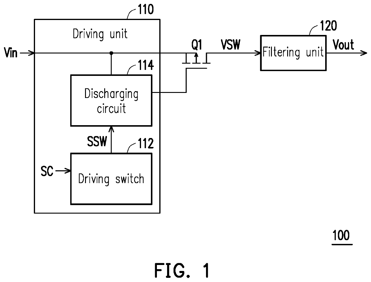
[0015]Referring to FIG. 1, FIG. 1 is a schematic diagram illustrating a soft-start control circuit in accordance with the invention. In the embodiment, a soft-start control circuit 100 includes a load switch Q1, a driving unit 110, and a filtering unit 120. The load switch Q1 may be realized as a switch in the form of a transistor. The load switch Q1 of the embodiment is realized as a P-type MOS field-effect transistor. The first terminal of the load switch Q1 is configured to receive an input voltage Vin. The control terminal of the load switch Q1 is configured to receive a switching signal SSW. The second terminal of the load switch Q1 is configured to provide a switched voltage VSW. The load switch Q1 may perform switching between on and off according to the switching signal SSW, thereby performing a soft-start operation. The switched voltage VSW is a voltage signal generated by converting the input voltage Vin according to the switching signal SSW by the load switch Q1. Therefor...
second embodiment
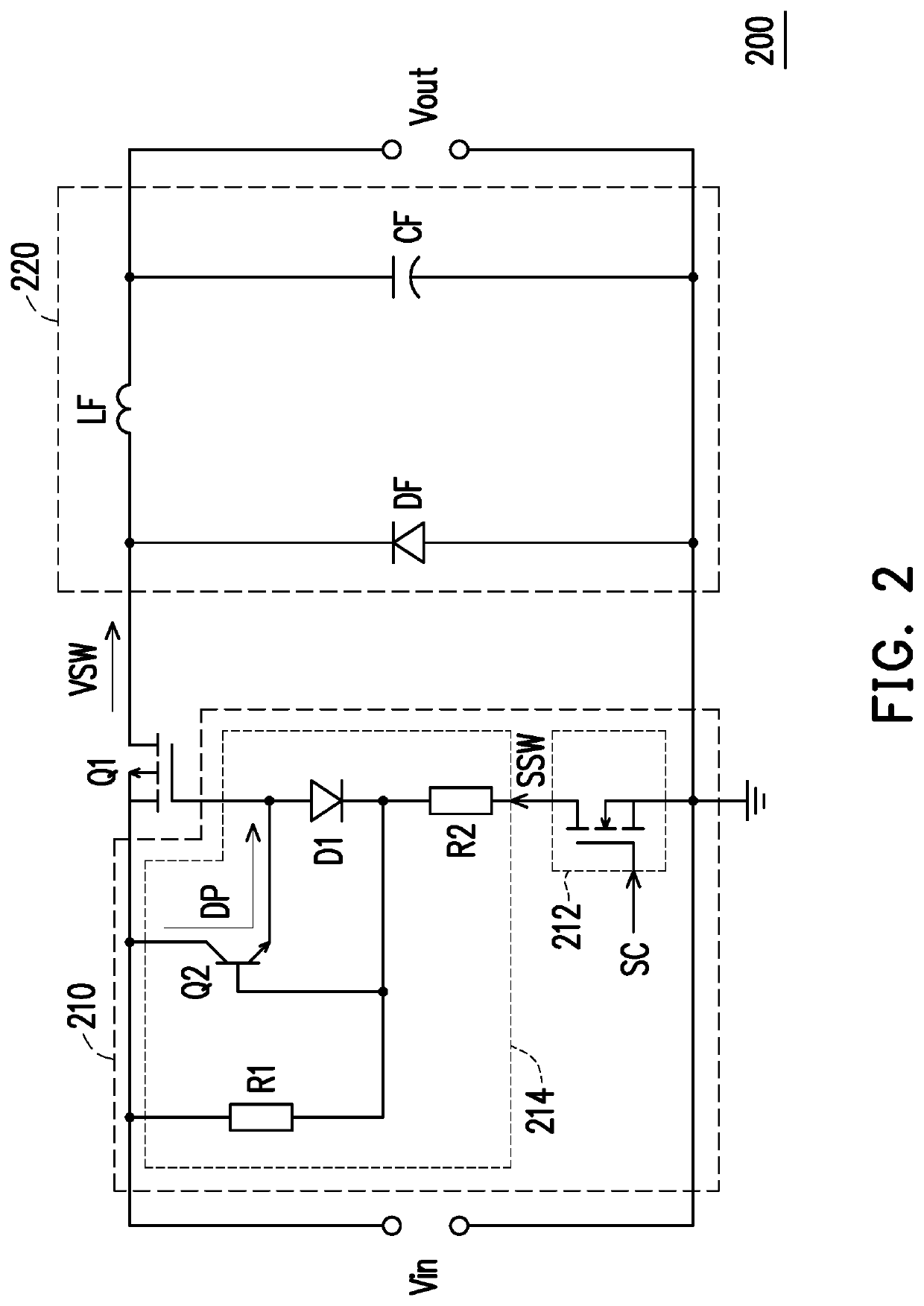
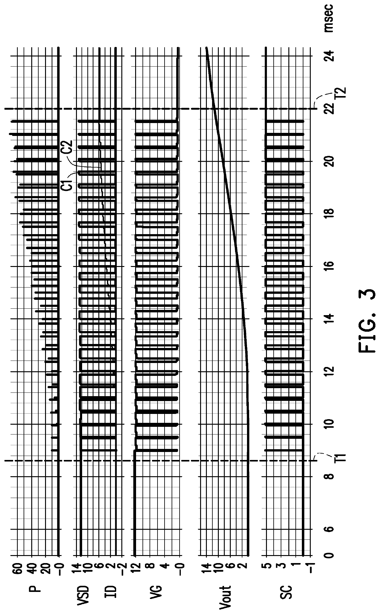
[0019]Referring to FIG. 2, FIG. 2 is a schematic diagram illustrating a soft-start control circuit in accordance with the invention. In the embodiment, a soft-start control circuit 200 includes a load switch Q1, a driving unit 210, and a filtering unit 220. The driving unit 210 includes a driving switch 212 and a discharging circuit 214. The driving switch 212 is realized as an N-type field-effect transistor or NPN bipolar transistor. The discharging circuit 214 includes a bipolar transistor Q2. The bipolar transistor Q2 is realized as an NPN bipolar transistor. The bipolar transistor Q2 includes a collector, an emitter, and a base. The collector of the bipolar transistor Q2 is coupled to the first terminal of the load switch Q1. The emitter of the bipolar transistor Q2 is coupled to the control terminal of the load switch Q1. In the embodiment, once the bipolar transistor Q2 is turned on, the bipolar transistor Q2 may form a discharging path DP connected between the first terminal ...
third embodiment
[0032]Referring to FIG. 4, FIG. 4 is a schematic diagram illustrating a soft-start control circuit in accordance with the invention. In the embodiment, a soft-start control circuit 300 includes a load switch Q1, a driving unit 310, and a filtering unit 320 and a protecting circuit 330. An operating of the load switch Q1, the driving unit 310, and the filtering unit 320 can be obtained at least from the embodiment in FIGS. 1, 2 and 3, and therefore is not repeated herein. In the embodiment, the protecting circuit 330 is coupled to the driving switch 312. The protecting circuit 330 pulls down a voltage level of the control signal SC according to an output current Iout. The output voltage Vout produces the output current Iout when receiving the output voltage Vout from the filtering unit 320. The protecting circuit 330 may receive the output current Iout and detect whether a current value of the output current Iout has an overcurrent phenomenon. The protecting circuit 330 may pull-down...
PUM
 Abstract
Description
Claims
Application Information
 - R&D
- Intellectual Property
- Life Sciences
- Materials
- Tech Scout
- Unparalleled Data Quality
- Higher Quality Content
- 60% Fewer Hallucinations
Browse by: Latest US Patents, China's latest patents, Technical Efficacy Thesaurus, Application Domain, Technology Topic, Popular Technical Reports.
© 2025 PatSnap. All rights reserved.Legal|Privacy policy|Modern Slavery Act Transparency Statement|Sitemap|About US| Contact US: help@patsnap.com


